
Inkjet printer and inkjet printing method

a technology of inkjet printing and printer, which is applied in the direction of printing, other printing apparatus, etc., can solve the problems of increasing the ejection volume although partially unsuitable for solving, and the image has high definition and high gradation, and achieves the reduction of density unevenness due to a deflection in the ejection direction, and high density.

Inactive Publication Date: 2009-03-24
CANON KK
View PDF11 Cites 8 Cited by
  • Summary
  • Abstract
  • Description
  • Claims
  • Application Information

AI Technical Summary

Benefits of technology

[0028]In order to solve the above problems, the present invention has been made. An object of the present invention is that an image having a high quality is output, in which density unevenness due to a deflection in an ejecting direction is reduced, in an inkjet printer for forming an image by ejecting small droplets of ink at a high frequency and high density.

Problems solved by technology

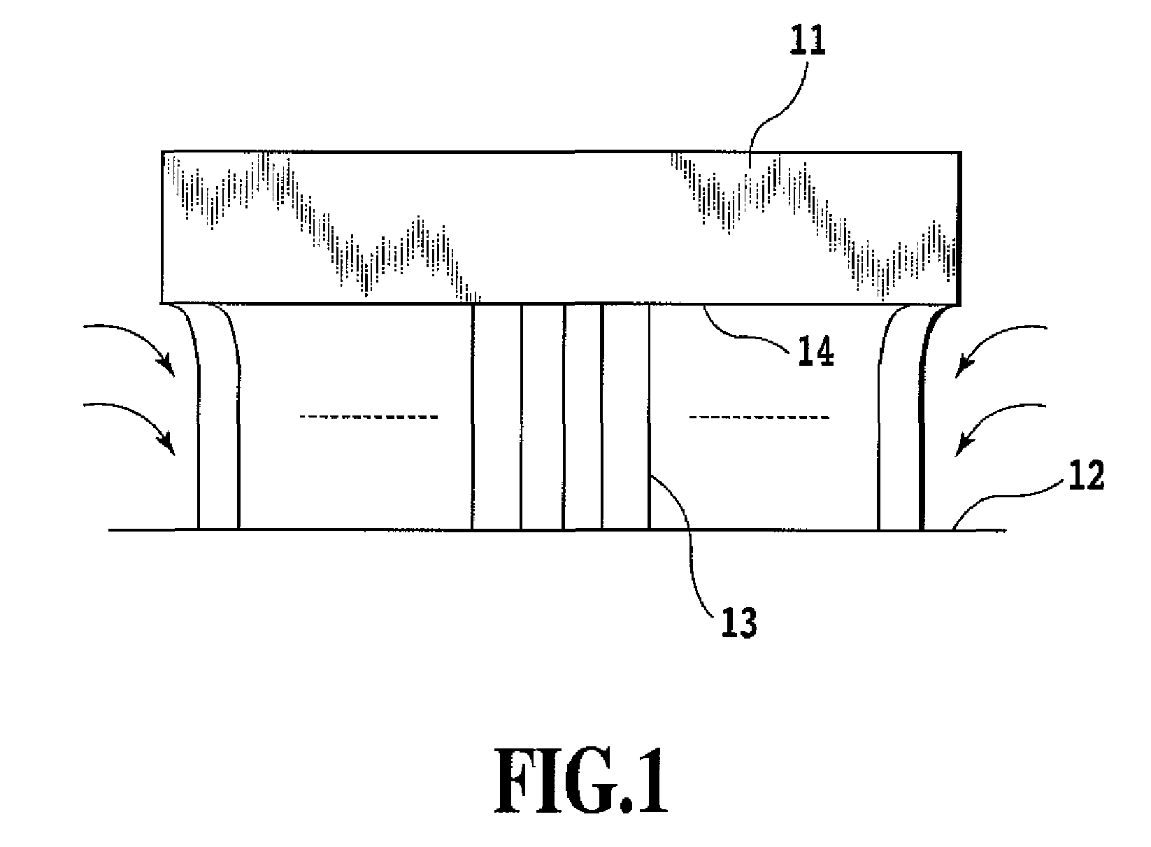
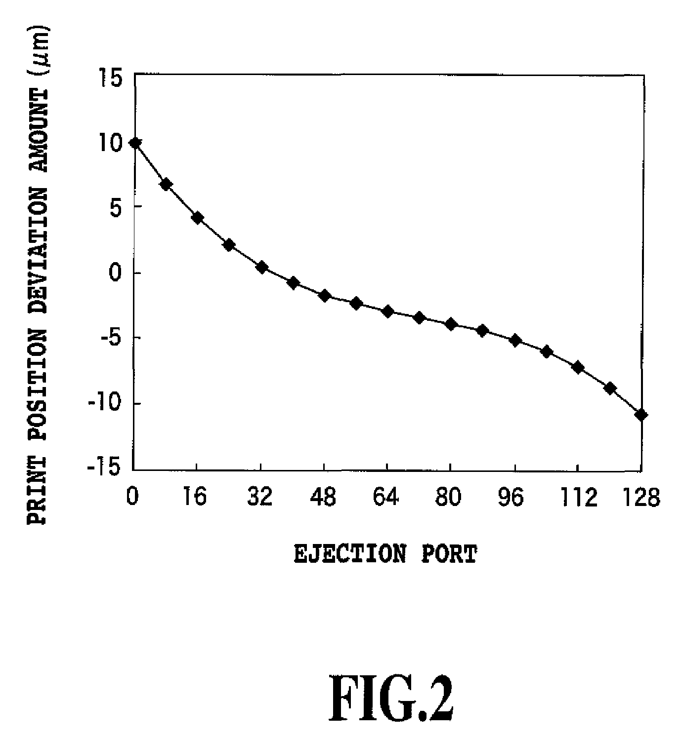
Under such circumstances, there has recently arisen a new problem called “end-deviation.”
However, making the ink droplets lager prevents an image having high definition and high gradation from being formed.
In the inkjet printer having the advantage of performing printing with small droplets of ink at a high definition, increasing the ejection volume although partially is not suitable as a solving method of the end-deviation.
Accordingly, in this case, an area arises in which the connecting part between the print scans excessively overlap with each other, and there is a risk that black streaks become conspicuous.
However, in the multi-pass printing method, printing is not performed for all printable pixels by only one print scanning.
Accordingly, even if there are variations in the ejecting direction and the ejection volume of the ejection ports, and even if there are some variations in conveying amount of the print medium, it is possible to make adverse effects due to the variations inconspicuous.
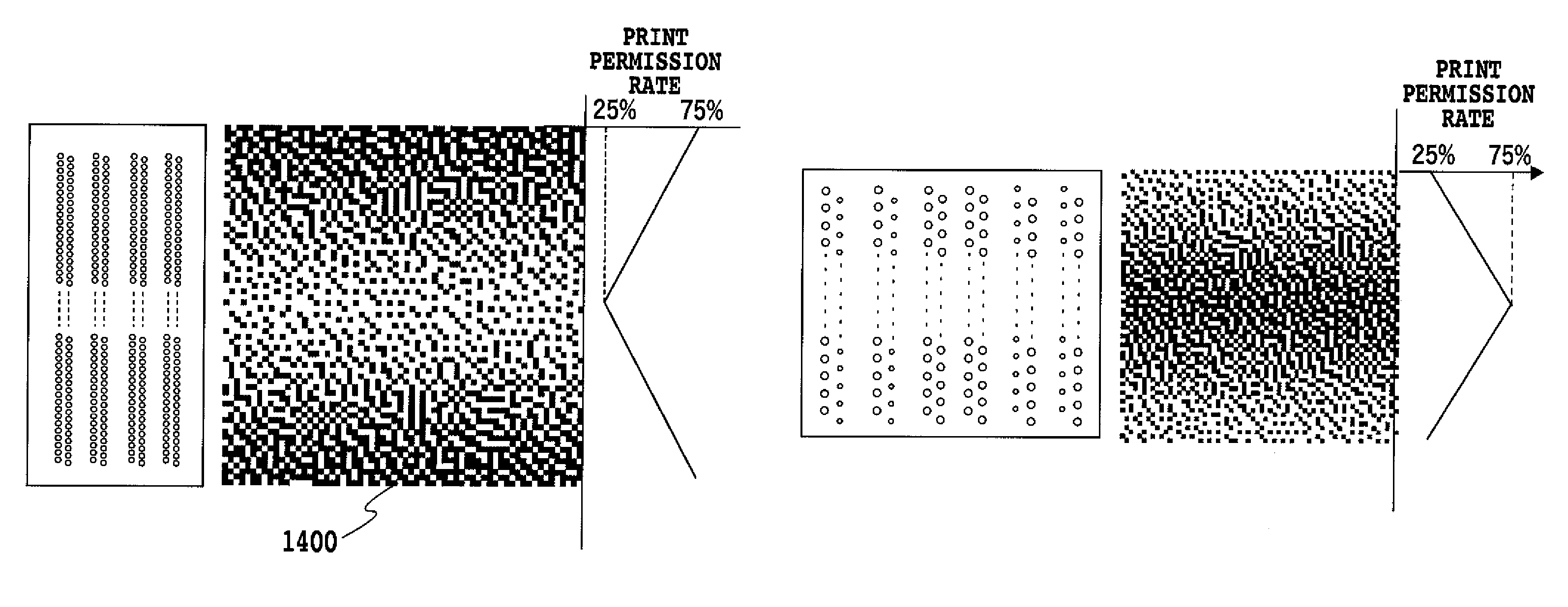
If the mask patterns shown in FIG. 6 are used which extremely reduce the print permission rate of the end area having few deviations and raises the print permission rate of the area having many deviations, adverse effects due to the density unevenness becomes more conspicuous.

Method used


Image

  • Inkjet printer and inkjet printing method
  • Inkjet printer and inkjet printing method
  • Inkjet printer and inkjet printing method

Examples


second embodiment

[0085]A second embodiment of the present invention will be described hereinafter. The inkjet printer and inkjet printing head as described with reference to FIG. 10 to FIG. 12 are used in the embodiment similarly to the first embodiment. However, the arrangement of each ejection port is different from that of the first embodiment.

[0086]FIG. 16 is a view of a printing head 1, which is observed from a ejection port surface side, used in the second embodiment. Twelve large and small ejection port arrays in total are arranged on a substrate of the embodiment, and 128 ejection ports are arranged in each ejection port array at pitches of 600 dpi. Ink droplets of 2.8 pl are ejected from ejection port arrays C1, C2, M1, M2, Y1, Y2, Bk1 and Bk2, and ink droplets of 0.6 pl are ejected from ejection port arrays C3, C4, M3 and M4. In addition, the cyan ink is ejected from the ejection port arrays C1, C2, C3 and C4, the magenta ink is ejected from the ejection port arrays M1, M2, M3 and M4, the ...


PUM


Abstract

An image having high quality is output, in which density unevenness due to a deflection in an ejecting direction is reduced, in an inkjet printer for forming an image by ejecting small droplets at a high frequency and high density. Thereby, in a mask pattern employed for multi-pass printing, a print permission rate of an ejection port positioned at the end of a ejection port array is set higher than those of ejection ports positioned at the other parts of the ejection port array. Thus, even if extremely small droplets are ejected at a high frequency and high-density, the generated density unevenness is reduced, and an image excellent in uniformity and having high definition can be output at a high speed.

Description

BACKGROUND OF THE INVENTION[0001]1. Field of the Invention[0002]The present invention relates to an inkjet printer and inkjet printing method, in particular, it relates to an inkjet printer and inkjet printing method for printing small droplet of ink at a high density and high frequency.[0003]2. Description of the Related Art[0004]Small droplet, high density nozzles and high driving frequencies have been promoted in inkjet printers. Under such circumstances, there has recently arisen a new problem called “end-deviation.”[0005]FIG. 1 is a schematic view showing an “end-deviation.” In FIG. 1, the reference numeral 11 denotes a printing head, and the printing head 11 vertically moves while ejecting ink droplets 13 from a plurality of ejection ports arranged at an ejection port surface 14 at a high density. The ejected ink droplets 13 impact a print medium 12 to form a dot. In a high ejecting frequency of the printing head, air with viscosity surrounding the ink droplets 13 move with a ...

Claims


Application Information

Patent Timeline
Patent Type & Authority Patents(United States)
IPC IPC(8): B41J29/38
CPCB41J2/2128
Inventor NOGUCHI, ERI
Owner CANON KK
Learn More