Card connector

Inactive Publication Date: 2009-03-24
CHENG UEI PRECISION IND CO LTD
View PDF3 Cites 22 Cited by
  • Summary
  • Abstract
  • Description
  • Claims
  • Application Information

AI Technical Summary

Benefits of technology

[0007]As described above, the propping sections elastically prop the card so as to generate a friction to the card. The friction generated thereby can slow down

Problems solved by technology

However, in the process of withdrawing the card from the card connector, for the above-mentioned card connector has no preventing members to slow down the speed

Method used


Image

  • Card connector
  • Card connector
  • Card connector

Examples


Embodiment Construction

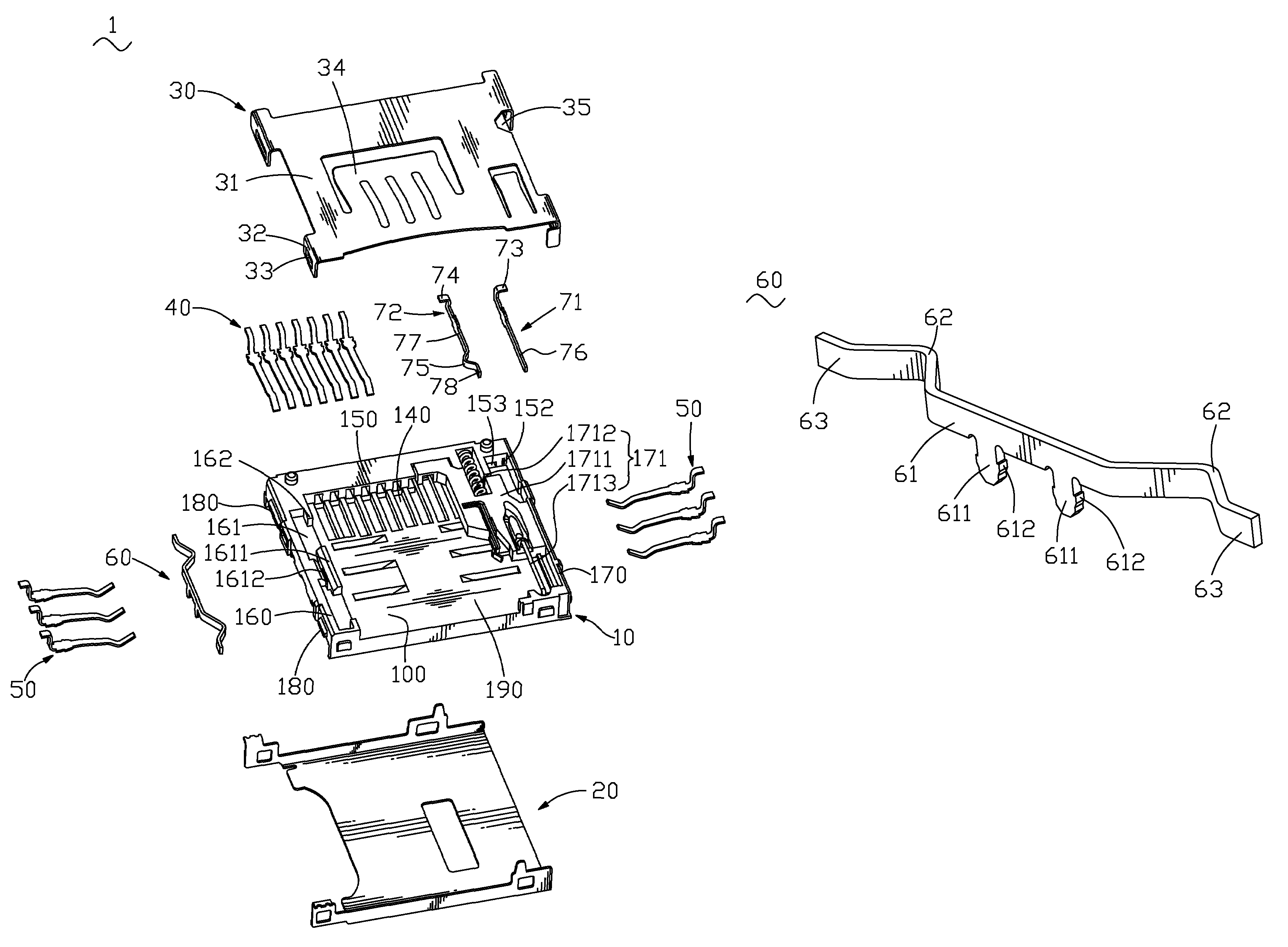
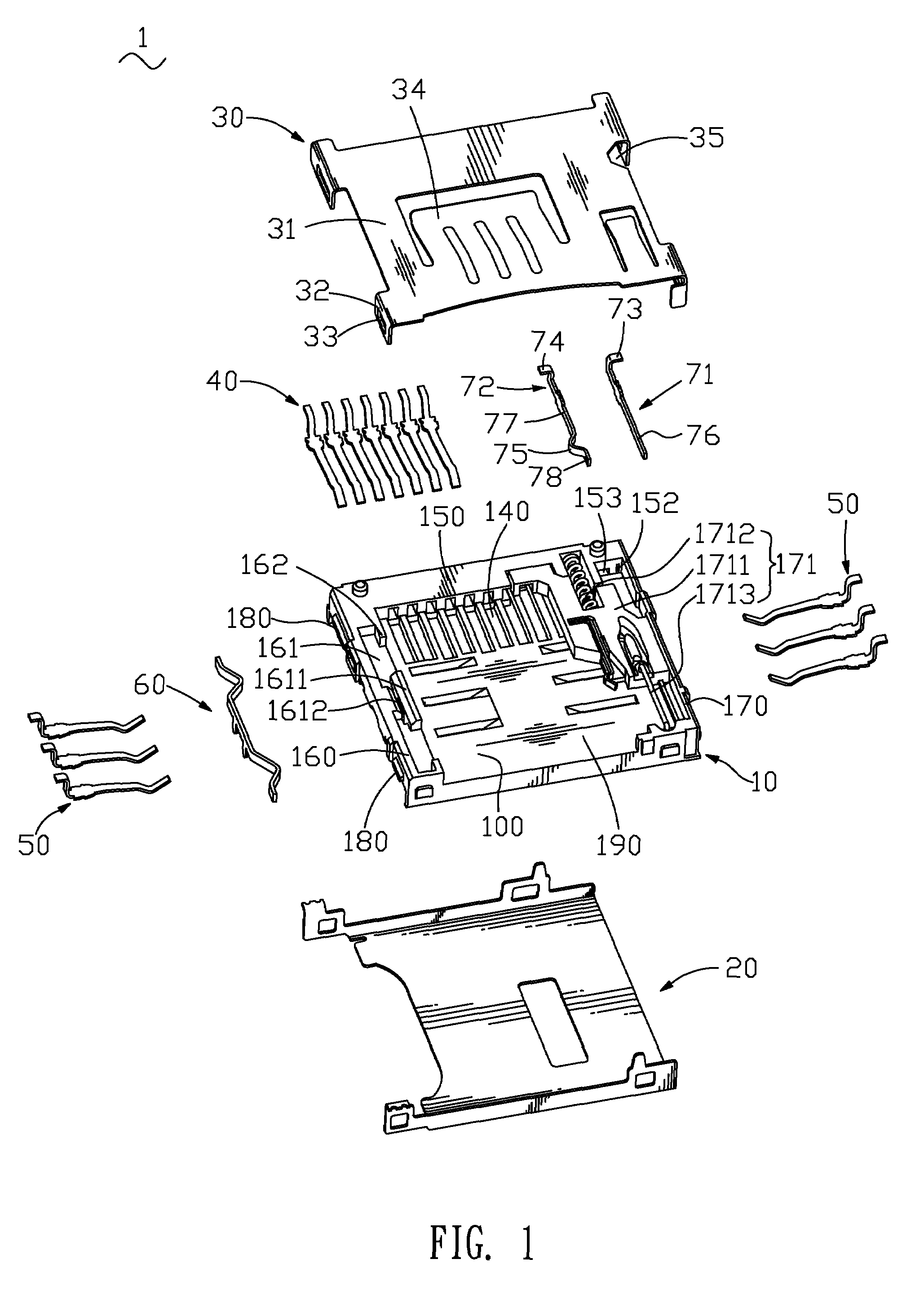
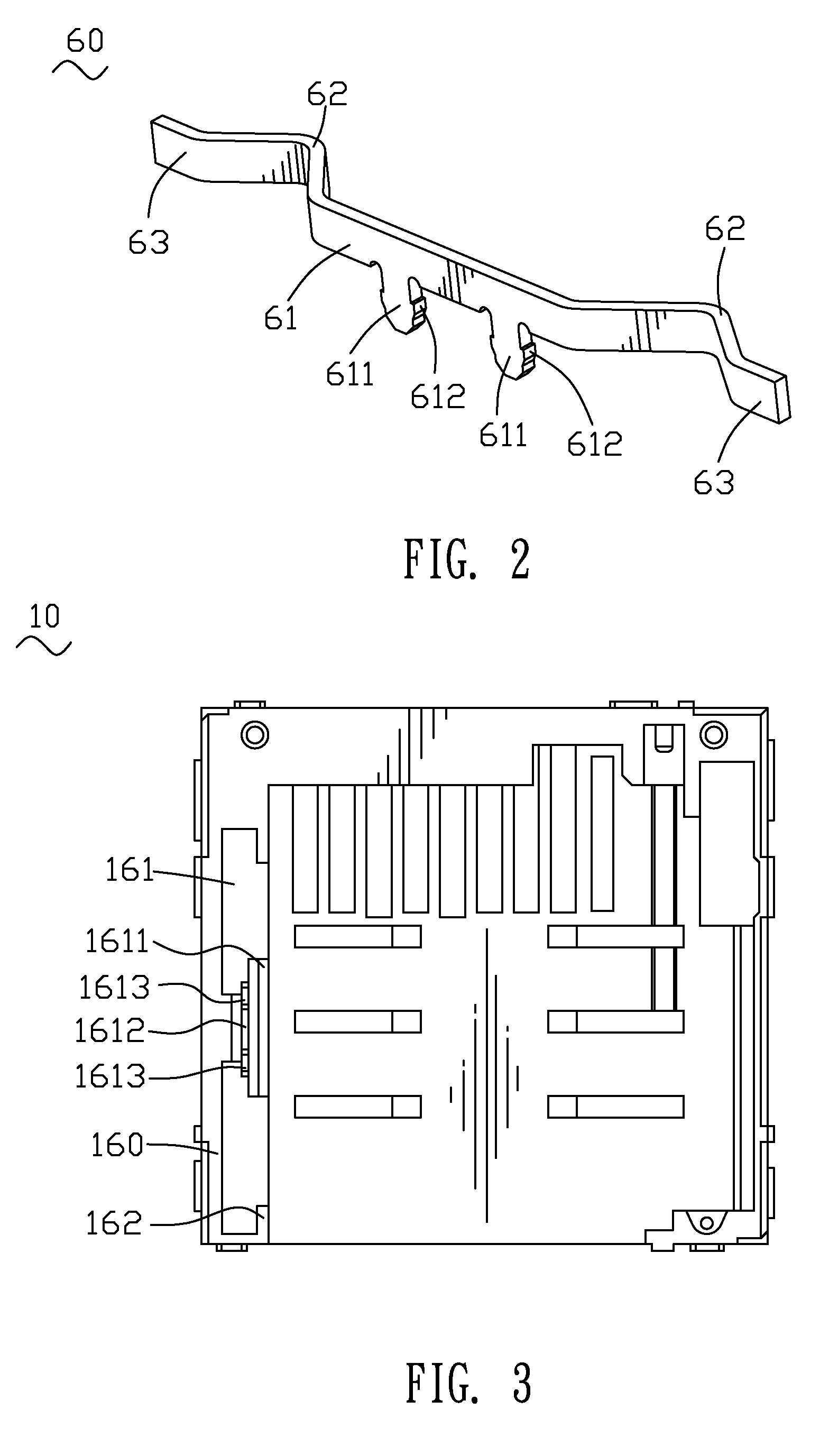
[0015]Referring to FIG. 1, a card connector 1 that is adapted for receiving two types of cards and allows the cards to be inserted thereinto from two different directions is shown. The card connector 1 includes an insulating housing 10, a bottom cover 20, a top cover 30, a plurality of first terminals 40, a plurality of second terminals 50 and a preventing member 60 held in the insulating housing 10.

[0016]Referring to FIG. 1 again, the insulating housing 10 has a rectangular base portion 100. Two opposite sides of the base portion 100 respectively extend upward to form a left sidewall 160 and a right sidewall 170. A rear wall 150 extends upward from the rear of the base portion 100. The left sidewall 160, the right sidewall 170 and the rear wall 150 define a first chamber 190 therebetween for receiving a first card 2 as best shown in FIG. 5. The rear of the base portion 100 longitudinally defines a plurality of first terminal cavities 140 penetrating through the rear wall 150 for re...


PUM


Abstract

A card connector includes an insulating housing, a plurality of terminals received in the insulating housing, a preventing member and an ejecting device. The insulating housing has a base portion. Two sidewalls extend upward from both sides of the base portion and a rear wall extends upward from the rear of the base portion. The sidewalls and the rear wall define a chamber therebetween for receiving a card. The preventing member is configured at one side of the insulating housing and has a base bar extending longitudinally. Two ends of the base bar protrude into the chamber to form a pair of propping sections for elastically propping one side of the card. The ejecting device is configured at the other side of the insulating housing opposite to the preventing member for operably withdrawing the card from the card connector.

Description

BACKGROUND OF THE INVENTION[0001]1. Field of the Invention[0002]The present invention relates to a card connector for receiving a card, and more particularly to a card connector capable of preventing the card from being shot off in the process of withdrawing the card from the card connector.[0003]2. The Related Art[0004]Traditionally, a card connector has an ejecting device used for withdrawing an external card from the card connector. The ejecting device includes a sliding body, a spring and a connecting bar. While the card is inserted into the card connector, the card pushes the sliding body to move. Then the spring is compressed and the connecting bar jostles the sliding body to make the sliding body and the spring relatively immovable. While the card is withdrawn from the card connector, the connecting bar departs from the sliding body. The power stored in the spring releases and drives the spring to reposition and further drives the sliding body to reposition. The sliding body ...

Claims


Application Information

Patent Timeline
IPC IPC(8): H01R13/62
CPCH01R13/633Y10S439/946
Inventor HUNG, PEI-CHIAO
Owner CHENG UEI PRECISION IND CO LTD
Why Eureka
Try Eureka