
Single scan track initiation for radars having rotating, electronically scanned antennas

a single scan and antenna technology, applied in the field of radar systems, can solve the problems of difficult tracking, difficult tracking, and conventional methods of track initiation, and achieve the effect of sufficient predictive validity

Inactive Publication Date: 2009-03-24
LOCKHEED MARTIN CORP
View PDF10 Cites 13 Cited by
  • Summary
  • Abstract
  • Description
  • Claims
  • Application Information

AI Technical Summary

Benefits of technology

Enables the determination of initial-tracks with sufficient predictive validity using only one scan's worth of detections, allowing radars to report new targets promptly and reduce the likelihood of false re-reporting, while improving target verification and tracking accuracy.

Problems solved by technology

Radar tracking is difficult, especially for air and missile targets—not only because of measurement errors, but also because of the wide variety of motion possible (with targets including, for example, helicopters, sub- and super-sonic aircraft, artillery, cruse and ballistic missiles).
Track initiation constitutes a difficult part of tracking since only a minimal set of detections exist at the beginning of a track.
Conventional methods for track-initiation tend not to work for this problem, as too few detections exist in one rotation period.
Furthermore, such detections span too short a time interval to provide initial-tracks with a requisite predictive validity.
This advanced antenna technology, however, brings new challenges to radar systems, and in particular, in determining an initial-track of a target that has sufficient predictive validity using only one scan's detections.
Rotation of the antenna prevents the radar from determining initial-tracks using only one scan's worth of detections—during one rotation period of the antenna the target might be detected only once and hence the detection cannot be verified.
Before determining the initial-track, given a new detection, the first problem the radar solves is that of confirming whether a detection proves to be a new target, as opposed to a detection that proves not to be a target referred to as a false alarm.
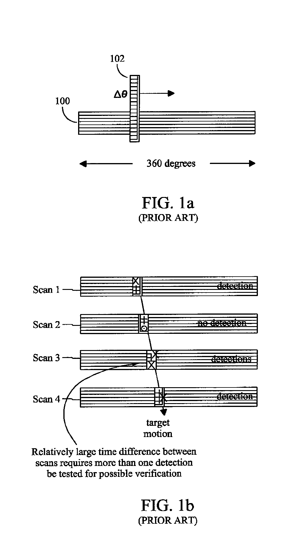
If, however, the time between the two detections is large, then the outcome may be inconclusive.
However, in FIG. 5b the two detections of the same target are not sufficiently close in time, in which case the unknown motion of the target manifests itself and defeats simplistic verification.
Thus, there is ambiguity as to whether one target does indeed exist, or whether there are two (unverified) targets; or that there are two false alarms, or that one target exists and that there is a false alarm.
Since the measurements have errors, the components of the state vector of an initial-track will also have errors.
This deficiency is caused by having to divide the differences of the position measurements by the small time interval they span, ΔT—the estimated velocity components become the difference of measurement errors divided by a small time increment.

Method used


Image

  • Single scan track initiation for radars having rotating, electronically scanned antennas
  • Single scan track initiation for radars having rotating, electronically scanned antennas
  • Single scan track initiation for radars having rotating, electronically scanned antennas

Examples


Embodiment Construction

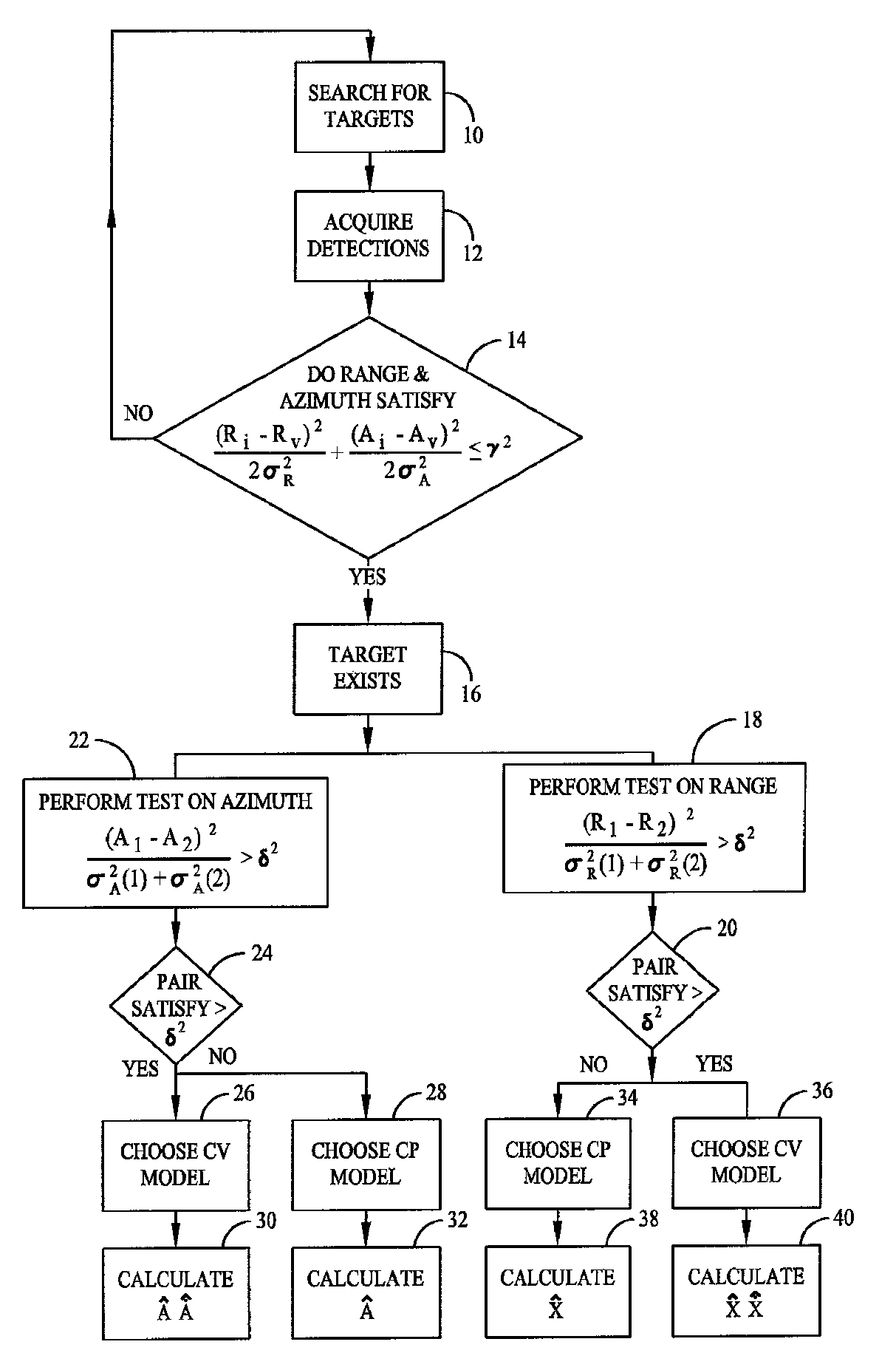
[0054]In the figures to be discussed, the circuits and associated blocks and arrows represent functions of the process according to the present invention, which may be implemented as electrical circuits and associated wires or data busses, which transport electrical signals. Alternatively, one or more associated arrows may represent communication (e.g., data flow) between software routines, particularly when the present method or apparatus of the present invention is a digital process. The invention described herein utilizes electronic processors, such as computers having data storage means, to process the data and perform mathematical computations using algorithms for accomplishing the stated goal: determination of an initial-track having sufficient predictive validity from one scan's worth of detections.

[0055]It is understood that the subject invention may reside in the program storage medium that constrains operation of the associated processors(s), and in the method steps that a...


PUM


Abstract

A method and radar system for detecting a target and verifying its presence to begin tracking and to enable future detections of the same target to be correctly associated with its initial detection uses two separate detections. Each detection provides three components of position measurements (range, elevation, and azimuth). The invention also pertains to an associated method for initiating a target track utilizing a rotating radar antenna having an electronic scanning antenna comprising the steps of: acquiring data representative of one or more of range, elevation and azimuth of a target, calculating target motion, forming multiple models for each degree of freedom of target motion, composing a set of initial state vectors that includes one having predictive validity for the realization of the true measurement errors and target motion.

Description

FIELD OF THE INVENTION[0001]This application relates generally to radar systems, and more particularly to air and missile defense radars having rotating, electronically scanned antennas.BACKGROUND OF THE INVENTION[0002]Radar tracking is difficult, especially for air and missile targets—not only because of measurement errors, but also because of the wide variety of motion possible (with targets including, for example, helicopters, sub- and super-sonic aircraft, artillery, cruse and ballistic missiles). Track initiation constitutes a difficult part of tracking since only a minimal set of detections exist at the beginning of a track. Conventional methods for track-initiation tend not to work for this problem, as too few detections exist in one rotation period. Furthermore, such detections span too short a time interval to provide initial-tracks with a requisite predictive validity.[0003]In general, air and missile defense radars use two types of antenna configurations: rotating antenna...

Claims


Application Information

Patent Timeline
Patent Type & Authority Patents(United States)
IPC IPC(8): G01S13/72
CPCG01S13/726G01S13/426
Inventor LESKIW, DONALD M.
Owner LOCKHEED MARTIN CORP
Learn More