
Method and apparatus for recording servo frame, storage disk, and method and apparatus for obtaining servo frame information

a technology of servo frame and storage disk, which is applied in the field of method and apparatus for recording servo frame, storage disk, and method and apparatus for obtaining servo frame information, can solve the problems of lowering the format efficiency, increasing the problematically, and increasing the data length of the servo frame 111, so as to reduce the reliability of the magnetic disk, the effect of shortening the data length

Active Publication Date: 2009-03-24
KK TOSHIBA
View PDF13 Cites 8 Cited by
  • Summary
  • Abstract
  • Description
  • Claims
  • Application Information

AI Technical Summary

Benefits of technology

The present invention aims to reduce the data length required for recording gray information and sector information on a storage disk without lowering reliability. The invention provides methods and apparatus for rearranging serial bits of sector information and track information, and performing an ExOR on the rearranged data to generate the track data for recording in a servo frame. The technical effects of the invention include reducing the size of the storage region required for the servo frame, improving format efficiency and efficiency of the magnetic disk, and improving reliability of the magnetic disk by easy detection and elimination of reading errors during a seeking operation.

Problems solved by technology

A raise in a servo sample rate requires an increase in the number of servo frames 111 but such an increase problematically lowers a format efficiency of a magnetic disk 110.
A conventional magnetic disk 110 however requires a long bit length for recording such gray information and sector information, and the data length of a servo frame 111 problematically lengthens.
That lowers a format efficiency.

Method used


Image

  • Method and apparatus for recording servo frame, storage disk, and method and apparatus for obtaining servo frame information
  • Method and apparatus for recording servo frame, storage disk, and method and apparatus for obtaining servo frame information
  • Method and apparatus for recording servo frame, storage disk, and method and apparatus for obtaining servo frame information

Examples


first embodiment

(A) First Embodiment

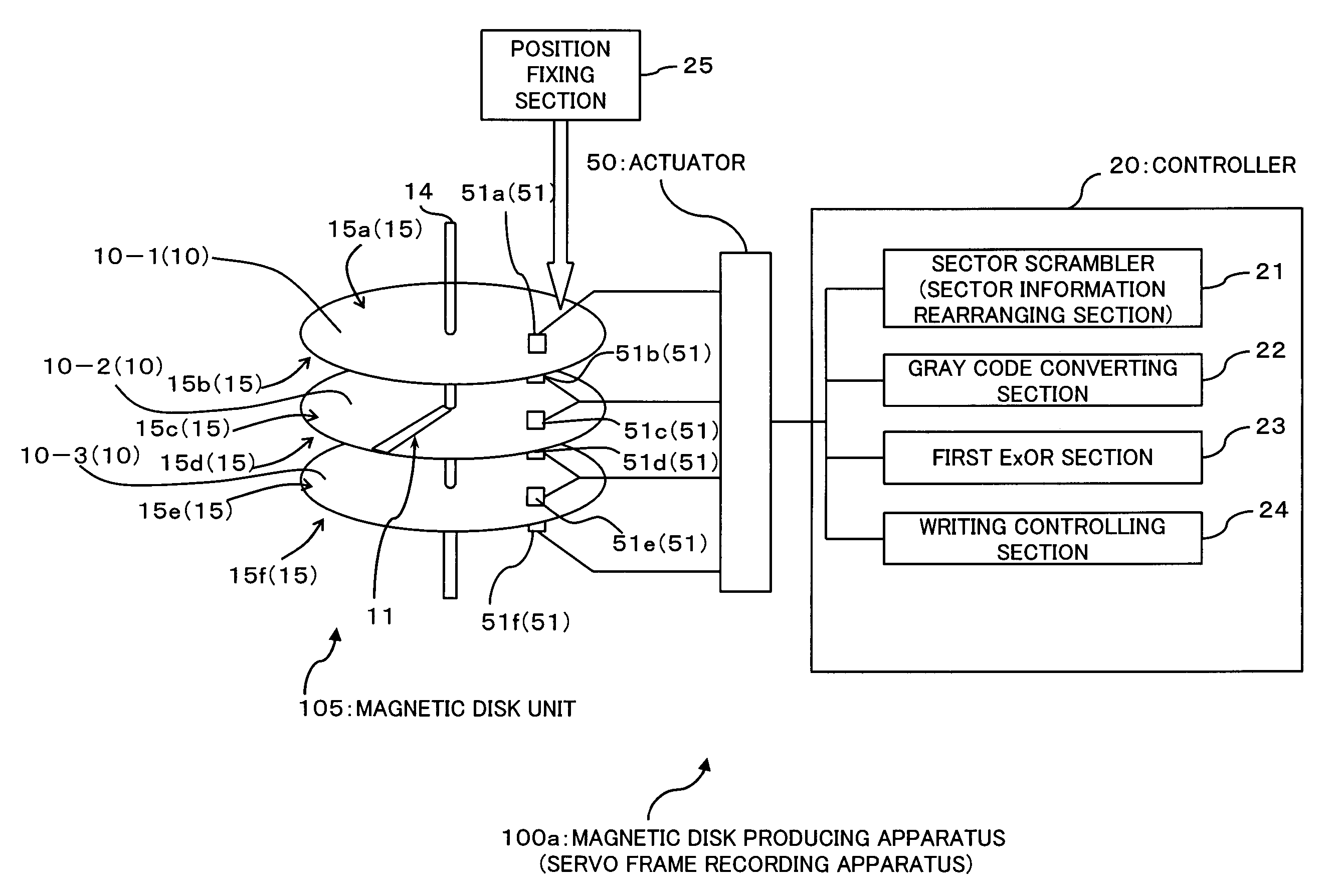
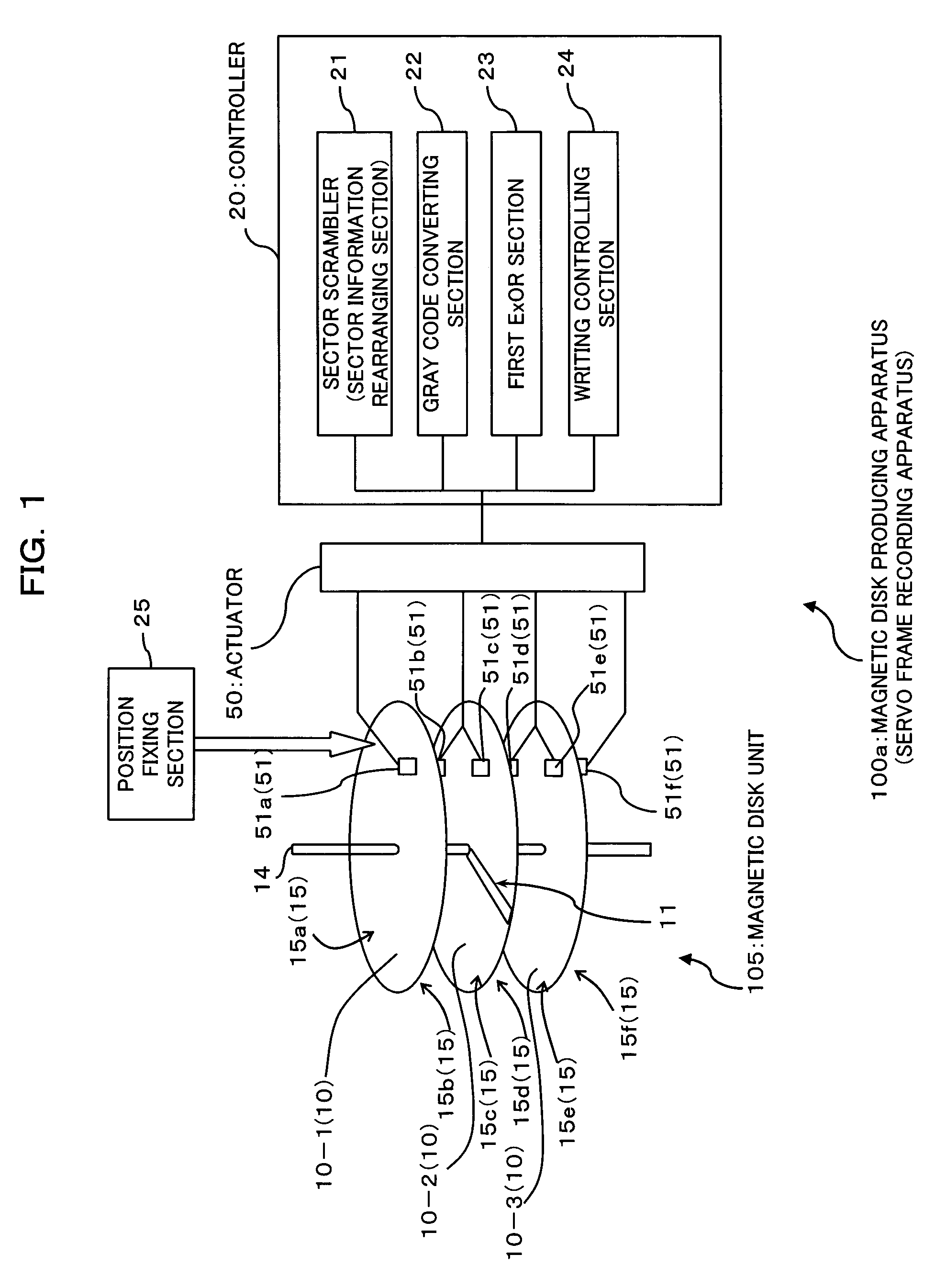
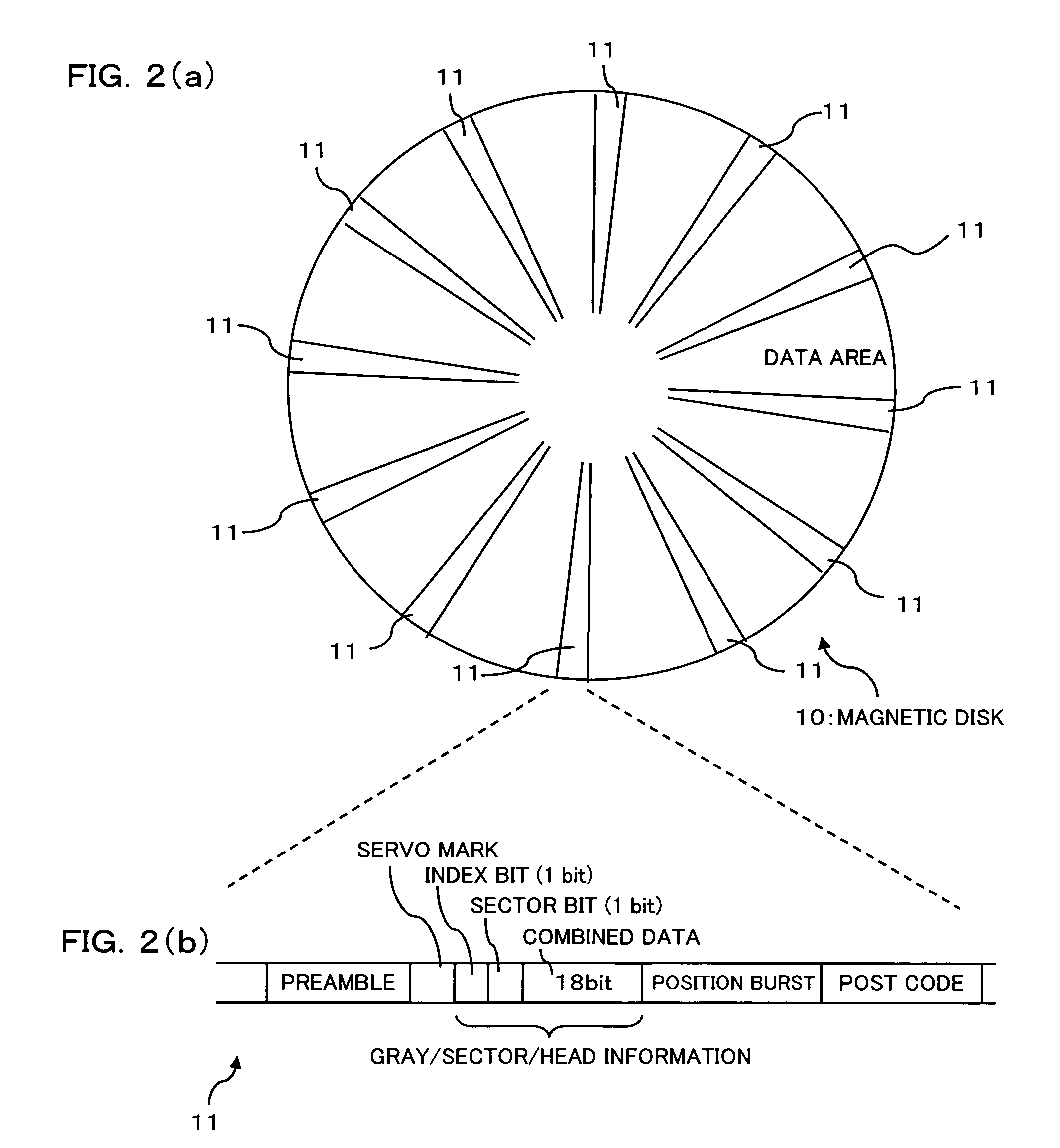
[0047]FIG. 1 is a block diagram schematically showing a configuration of a magnetic disk producing apparatus (a servo frame recording apparatus) according to the first embodiment of the present invention. FIGS. 2(a) and 2(b) are diagrams illustrating a configuration of a magnetic disk produced by the magnetic disk producing apparatus; more specifically, FIG. 2(a) schematically shows a configuration of a magnetic disk and FIG. 2(b) schematically shows a configuration of a servo frame formed on the magnetic disk. FIG. 3 is a block diagram schematically showing a configuration of a magnetic disk apparatus including the magnetic disk shown in FIGS. 2(a) and 2(b).

[0048]In the first embodiment, a magnetic disk producing apparatus 100a produces a magnetic disk unit 105 included in a magnetic disk apparatus la shown in FIG. 3. The magnetic disk unit 105 includes three magnetic disks 10-1, 10-2, 10-3 (see FIG. 2).

(A-1) Description of a Magnetic Disk

[0049]The magnetic disk...

second embodiment

(B) Second Embodiment

[0117]FIG. 10 is a block diagram schematically showing a magnetic disk producing apparatus (a servo frame recording apparatus) according to a second embodiment of the present invention; and FIG. 11 is a block diagram schematically showing a magnetic disk apparatus according to the second embodiment.

[0118]The magnetic disk producing apparatus 100b also produces a magnetic disk unit 105 that is to be incorporated in a magnetic disk apparatus 1b shown in FIG. 11. The magnetic disk unit 105 includes three magnetic disks 10-1, 10-2, 10-3 (see FIG. 2).

[0119]Parts and elements in accompanying drawings with reference numbers identical to those previously referred are identical or substantially identical parts and elements, so repetitious detailed description is omitted here.

(B-1) Description of the Magnetic Disk Producing Apparatus

[0120]The magnetic disk producing apparatus 100b of the second embodiment, as shown in FIG. 10, includes a controller 20 having a function as...


PUM

PropertyMeasurementUnit
circumferenceaaaaaaaaaa
densityaaaaaaaaaa
recording densityaaaaaaaaaa

Abstract

A servo-frame recording apparatus includes: a sector information rearranging section for rearranging serial bits of the sector information that is binary data; a first ExOR section for performing the ExOR (exclusive OR) on the sector information, the serial bits of which have been rearranged by said sector information rearranging section, and the track information, so that an exclusive logical sum is obtained; and a writing section for wiring the exclusive logical sum obtained by said ExOR section into the servo frame. With this configuration, a data length required for recording gray information and sector information can be shortened without lowering the reliability of a magnetic disk.

Description

BACKGROUND OF THE INVENTION[0001]1. Field of the Invention[0002]The present invention relates to a technique to recode gray information and sector information into a servo frame region formed on a magnetic disk.[0003]2. Description of the Related Art[0004]Accompanying drawings FIGS. 15(a) and 15(b) illustrate a configuration of a conventional magnetic disk; FIG. 15(a) schematically illustrates a configuration of a conventional magnetic disk and FIG. 15(b) schematically shows a configuration of a servo frame formed on the magnetic disk of FIG. 15(a).[0005]A conventional magnetic disk 110, as shown in FIG. 15(a), takes the form of a platter one side or the both sides of which serve recording layer covered with a magnetic material, and a non-illustrated magnetic head reads information from and write information into a surface (a storage region) of the magnetic disk 110.[0006]On the magnetic disk 110, a number of servo frames 111 are radially formed so as to stretch from the center to t...

Claims


Application Information

Patent Timeline
Patent Type & Authority Patents(United States)
IPC IPC(8): G11B5/09
CPCG11B20/1217G11B20/1426G11B27/3027G11B2020/1265G11B2020/1284G11B2220/2516G11B20/10G11B5/09
Inventor KOSUGI, TATSUHIKOKAGAMI, YOSHIYUKI
Owner KK TOSHIBA
Learn More