Motorized pyrotechnic system

a pyrotechnic system and motorized technology, applied in the direction of aerial display rockets, firecrackers, weapons, etc., can solve the problem of limited range of pyrotechnic displays currently achievable with gerbs

Active Publication Date: 2009-03-31
STRICTLY FX LLC
View PDF32 Cites 16 Cited by
  • Summary
  • Abstract
  • Description
  • Claims
  • Application Information

AI Technical Summary

Benefits of technology

[0006]One aspect of the invention provides a firing apparatus that includes a motor, an enclosure housing the motor and an arm including a proximal end that is attached to a shaft of the motor that projects through the enclosure, a distal end adapted to receive a pyrotechnic device and a body portion including an ignition contact for firing the pyrotechnic device. The enclosure includes a motor control interface for receiving a signal from a control unit located remotely from the firing apparatus for operating the motor and an ignition interface connected with the ignition

Problems solved by technology

While gerbs are commonly available and generally inexpensive, the range o

Method used


Image

  • Motorized pyrotechnic system
  • Motorized pyrotechnic system
  • Motorized pyrotechnic system

Examples


Embodiment Construction

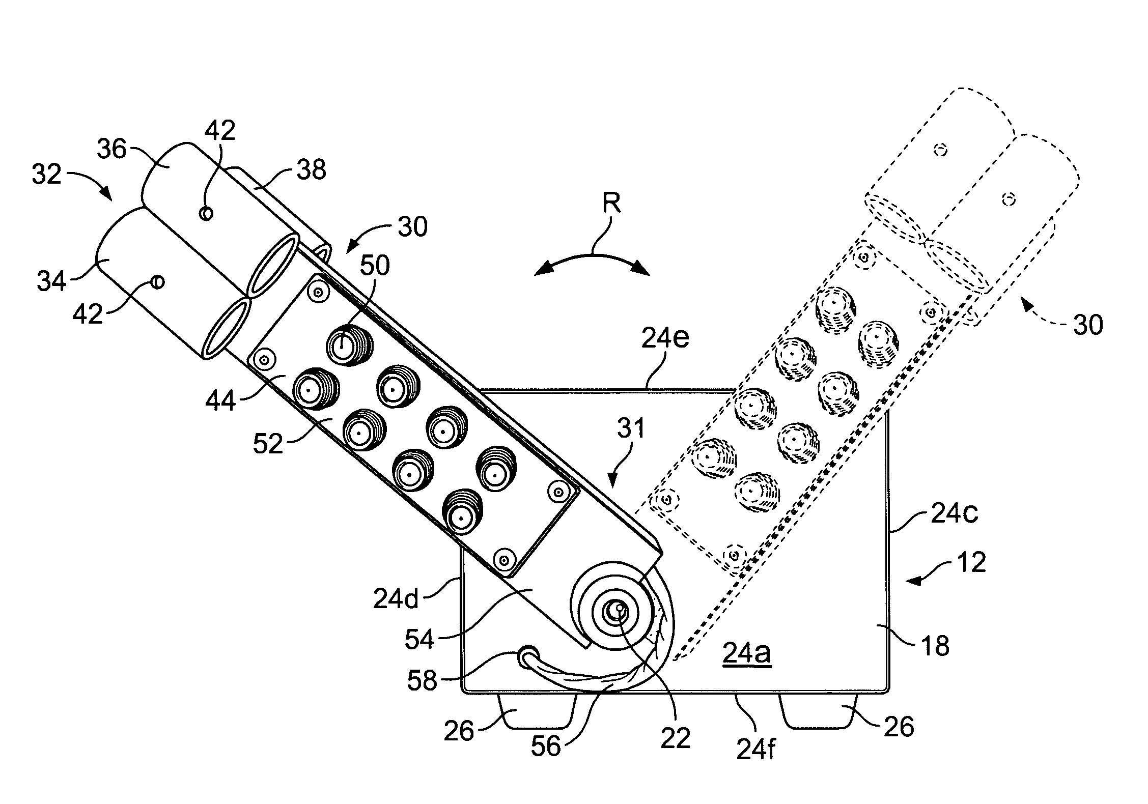
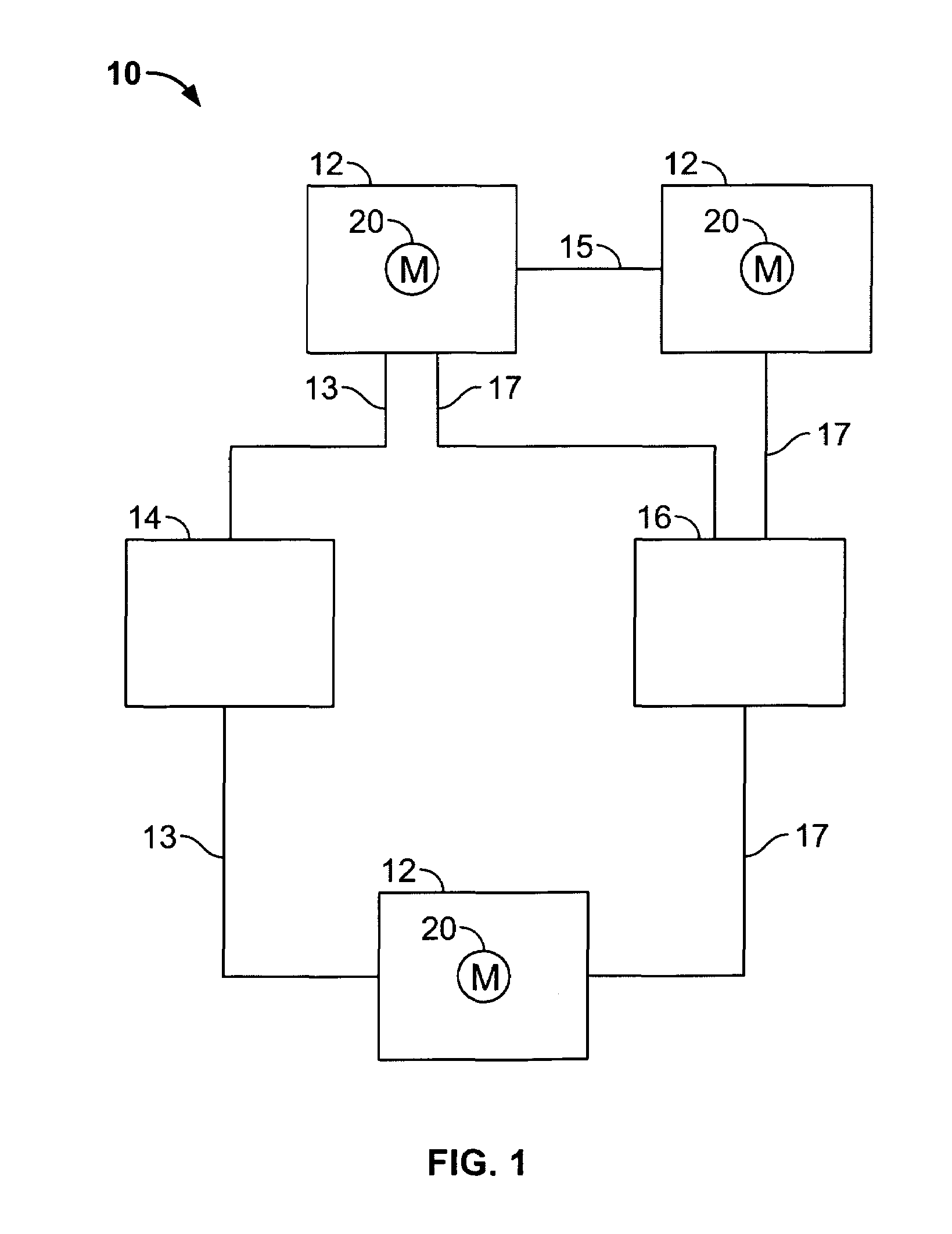
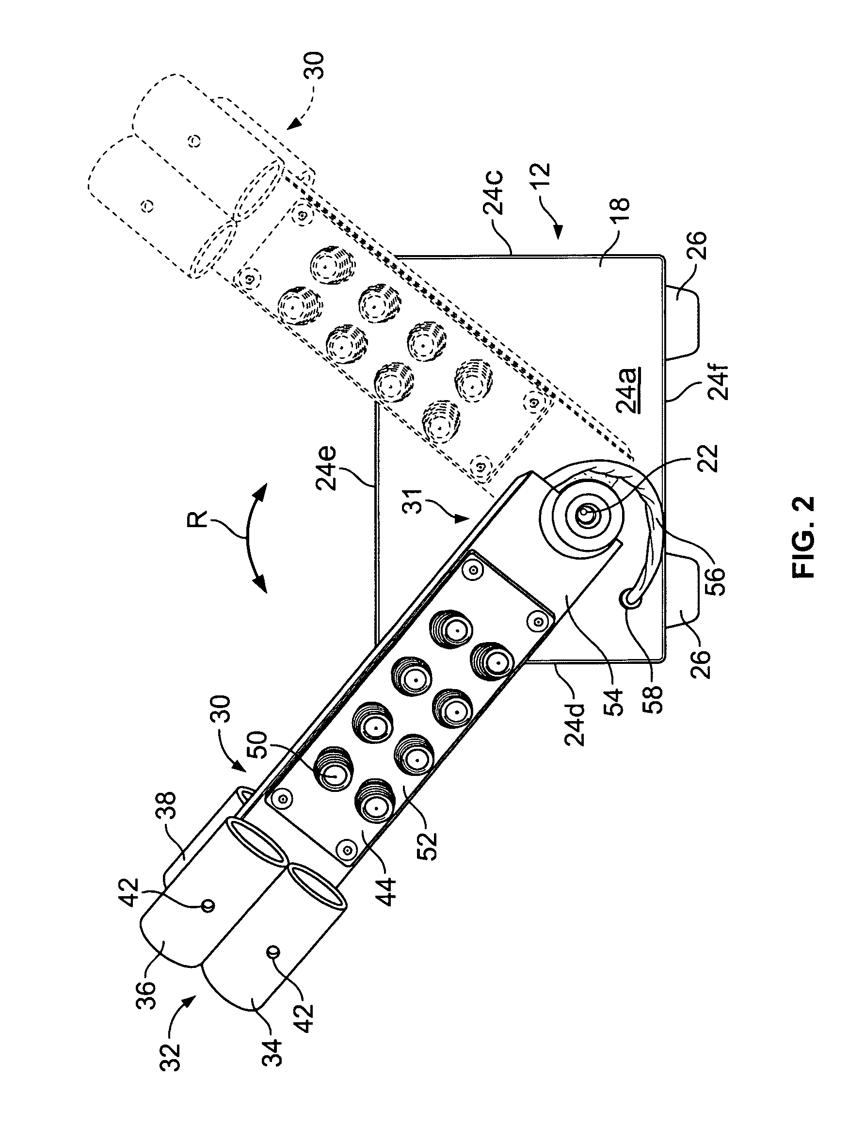
[0015]Referring now to the Figures and particularly to FIG. 1, a motorized pyrotechnic system 10 is provided. As shown, the motorized pyrotechnic system 10 includes one or more firing apparatuses 12 for producing a visual effect, a control unit 14 for operating the firing apparatuses 12 and an ignition unit 16. Each of the firing apparatuses 12 includes a motor 20 for movement of a pyrotechnic device (e.g., a gerb) to produce a visual effect. An example firing apparatus 12 is illustrated in FIGS. 2-4 and discussed hereafter in further detail. The control unit 14 is linked with each firing apparatus 12 by a wired link 13 for providing one or more of operational power and control signals to the motor 20 for producing a desired visual effect with the pyrotechnic device. Although the control unit 14 is illustrated as communicating with each firing apparatus 12 via a wired link 13 (e.g., a patch cord, cable or the like), the control unit may alternatively communicate with one or more of ...


PUM


Abstract

One aspect of the invention provides a firing apparatus that provides an arcuate visual effect. The firing apparatus includes a motor, an enclosure housing the motor and an arm connected to a shaft of the motor for moving a pyrotechnic device such as a gerb. Another aspect of the invention provides a pyrotechnic system that includes a firing apparatus including a reciprocal motor, a firing arm having a first end connected to a shaft of the reciprocal motor and a second end adapted to emit an arcuate pyrotechnic effect, a control unit in communication with the firing apparatus for controlling operation of the reciprocal motor and an ignition unit in communication with the firing apparatus for initiating the pyrotechnic effect.

Description

FIELD OF THE INVENTION[0001]The present invention relates generally to systems and methods for providing visual effects, and more particularly to a motorized pyrotechnic system.BACKGROUND OF THE INVENTION[0002]The fireworks industry has employed black powder-based pyrotechnic compositions in both stationary and projectile forms in the past to produce various different types of pyrotechnic displays. One common pyrotechnic that is used in pyrotechnic displays is a “gerb.”[0003]As known in the art, a gerb is a tube that is sealed at one end, has a nozzle at the other end and is filled with a pyrotechnic mixture containing at least an oxidant and a fuel. A gerb is somewhat similar to a rocket, providing a pyrotechnic effect that is similar to a vertical spray or fountain of flame, sparks or stars. However, unlike a rocket, a gerb is typically used as a stationary portion of a set piece and does not move. As is known, the nozzle, choke or restriction portion of the gerb increases the int...

Claims


Application Information

Patent Timeline
IPC IPC(8): F42B4/06
CPCF41F3/04F42B4/06
Inventor NOFSINGER, REIDGREGA, MARK J.
Owner STRICTLY FX LLC
Why Eureka
Try Eureka