Body cover structure for seat type vehicle

a seat type and body cover technology, applied in the direction of roofs, cycle equipment, transportation and packaging, etc., can solve the problem of difficult to form a non-slip portion, and achieve the effect of reducing the risk of the feet of the driver and reducing the manufacturing cos

Active Publication Date: 2009-03-31
HONDA MOTOR CO LTD
View PDF10 Cites 46 Cited by
  • Summary
  • Abstract
  • Description
  • Claims
  • Application Information

AI Technical Summary

Benefits of technology

[0010]According to this construction, the floor surface can be formed separately from the front cover, thereby making it possible to form a non-slip portion on the floor surface between the tire housings.
[0014]According to this construction, the molding die for the front cover can be split in the longitudinal direction of the vehicle, thereby making it possible to form the footrest portion integrally in the front cover.
[0015]According to the present invention, since the floor surface can be formed integrally with the center cover, by splitting the molding die for the center cover in the vertical direction of the vehicle, a non-slip portion can be formed on the floor surface located between the tire housings. Therefore, it is possible to reduce the risk of the feet of the driver or the like slipping on the floor surface. On the other hand, since the footrest portion is formed integrally in each of the tire housings of the front cover, there is no need to form the footrest portion as a separate component from the front cover, thereby allowing a reduction in manufacturing cost. Further, the footrest portion can be formed at a position higher than the floor surface of the center cover.

Problems solved by technology

Thus, it has been difficult to form a non-slip portion that protrudes in the vertical direction of the vehicle in the floor surface between the tire housings of the front cover.

Method used


Image

  • Body cover structure for seat type vehicle
  • Body cover structure for seat type vehicle
  • Body cover structure for seat type vehicle

Examples


Embodiment Construction

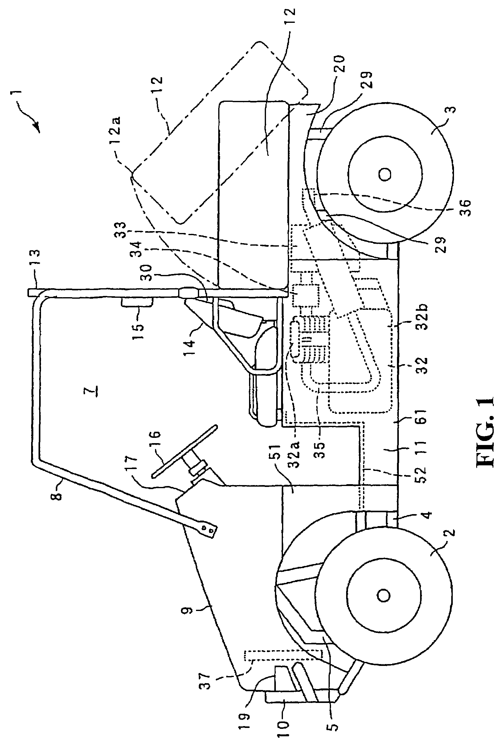
[0030]A body cover structure for a seat type vehicle according to an embodiment of the present invention will now be described with reference to the drawings.

[0031]It should be noted that in this embodiment, a MUV (Multi Utility Vehicle) will be described as an example of the seat type vehicle. Further, in the following description, as for the up, down, front, and rear directions, the front side refers to the left-hand side as seen in FIG. 1, and the left and right directions refer to the directions as seen by the driver when seated in the occupant seat.

[0032]As shown in FIG. 1, a MUV vehicle 1 is a four-wheel vehicle capable of driving over rough terrain or the like and having two front wheels 2 and two rear wheels 3 provided on the front and rear sides, respectively.

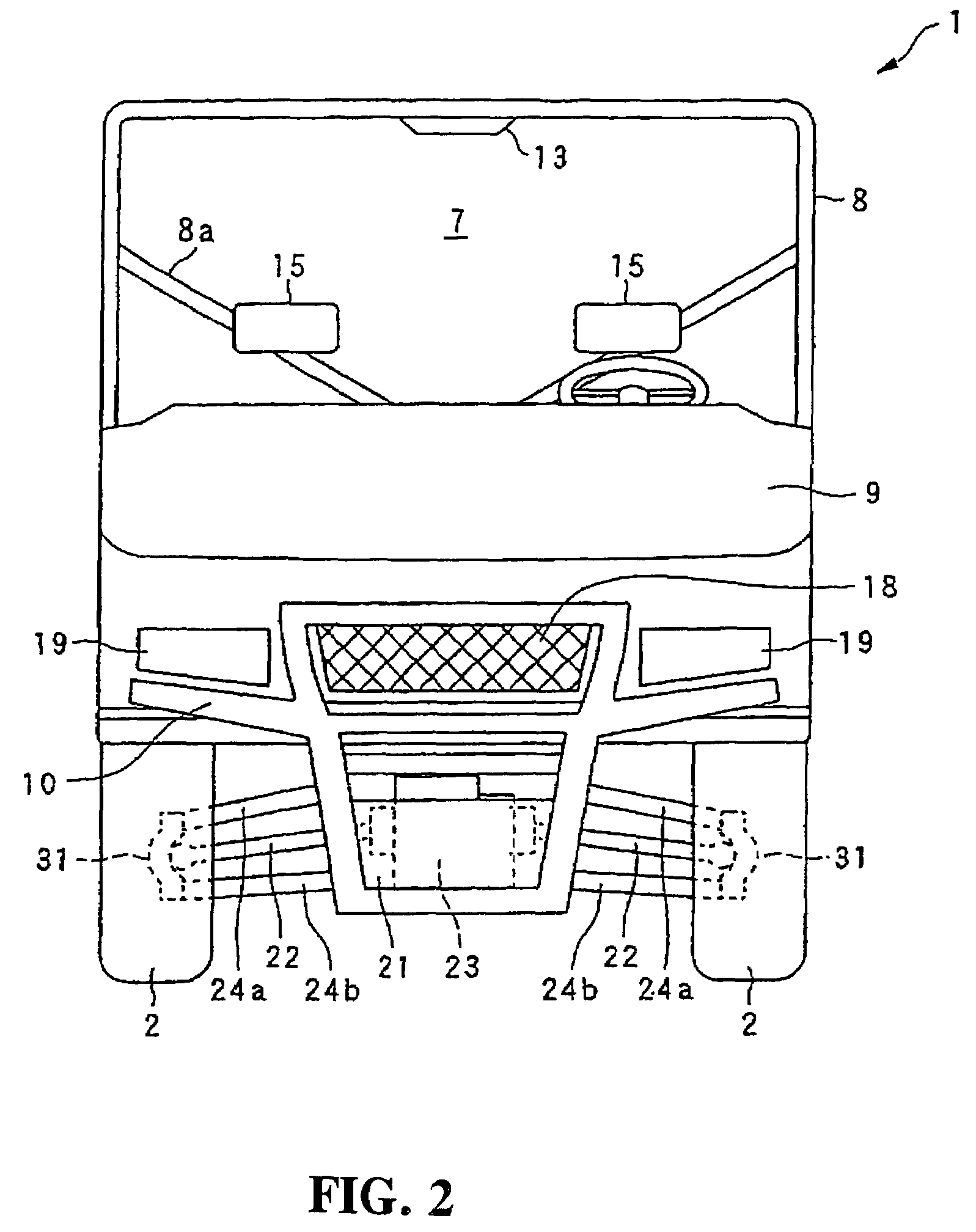
[0033]As shown in FIGS. 1 and 2, at the front portion of the vehicle 1, there are provided a bonnet 9 attached by means of a hinge or the like so as to freely open and close in the vertical direction with a front grill...


PUM


Abstract

A body cover structure for a seat type vehicle provides a non-slip portion that can be formed integrally on a floor surface located between the tire housings. In a body cover structure for a seat type vehicle in which a body cover made of resin that covers a body frame is split into a front cover, a center cover, and a rear cover, and in which tire housings are formed in the front cover, a floor panel portion extends between tire housings and is formed integrally in the center cover. Non-slip portions are integrally formed on the floor surface of the floor panel portion.

Description

CROSS-REFERENCE TO RELATED APPLICATIONS[0001]The present application claims priority under 35 USC 119 to Japanese Patent Application No. 2006-096578 filed on Mar. 31, 2006 the entire contents of which are hereby incorporated by reference.BACKGROUND OF THE INVENTION[0002]1. Field of the Invention[0003]The present invention relates to a body cover structure for a seat type vehicle that is formed so as to include tire housings located on the left and right front sides of a cab.[0004]2. Description of Background Art[0005]A MUV (Multi Utility Vehicle) vehicle is commonly known as a seat type vehicle capable of driving over rough terrain places or the like. A vehicle of this type is equipped with a body cover constituting the front lower portion and side portions of a cab. The body cover includes a front cover having left and right tire housings, a center cover extending rearward from a lower portion of the front cover, and a rear cover constituting a portion on the further rear side from...

Claims


Application Information

Patent Timeline
Patent Type & Authority Patents(United States)
IPC IPC(8): B62D25/00B62D25/20
CPCB60N3/06B62D23/005B62D25/2018B62D29/043B62D31/003
Inventor KOBAYASHI, TAKESHIKAWAGUCHI, YUKINORIINOUE, MASAHIRO
Owner HONDA MOTOR CO LTD
Why Eureka
Try Eureka