Machine for milling traffic areas

a technology for traffic areas and machines, applied in slitting machines, roads, constructions, etc., can solve the problem of people moving into the hazard area at the side of the machine, and achieve the effect of simple manner

Inactive Publication Date: 2009-03-31
ABG ALLG BAUMASCHINEN GMBH
View PDF18 Cites 28 Cited by
  • Summary
  • Abstract
  • Description
  • Claims
  • Application Information

AI Technical Summary

Benefits of technology

[0006]An object of the invention is to provide a machine for milling traffic areas in which monitoring of the hazard region of the machine and height regulation can be carried out in a simple manner.
[0007]Accordingly, a machine for milling traffic areas comprising a vertically adjustable chassis is provided, which chassis carries a steerable travelling mechanism and a drive unit for moving the machine and for driving a milling mechanism coupled to the drive unit, a laser scanner being attached at least on one side of the chassis, with which laser scanner the height relative to the surface of a traffic area to be milled can be measured and the chassis can be set vertically in accordance with the measured values relative to the surface of the traffic area to be milled, the laser scanner being attached in the centre side-wall region of the chassis with its scanning plane essentially parallel to the side-wall region of the chassis and at a height which permits monitoring of a hazard region which extends at least over the side length of the machine and producing a trigger signal if a disturbance occurs in the scanning plane. In this way, the laser scanner performs a double function which, in addition to the height regulation, results in monitoring of the hazard region without substantial cost.

Problems solved by technology

In addition, in the case of machines for milling traffic areas, there is the problem that persons can move into the hazard region at the side of the machine, in particular at road edges, without being noticed by the driver of the machine.

Method used


Image

  • Machine for milling traffic areas
  • Machine for milling traffic areas

Examples


Embodiment Construction

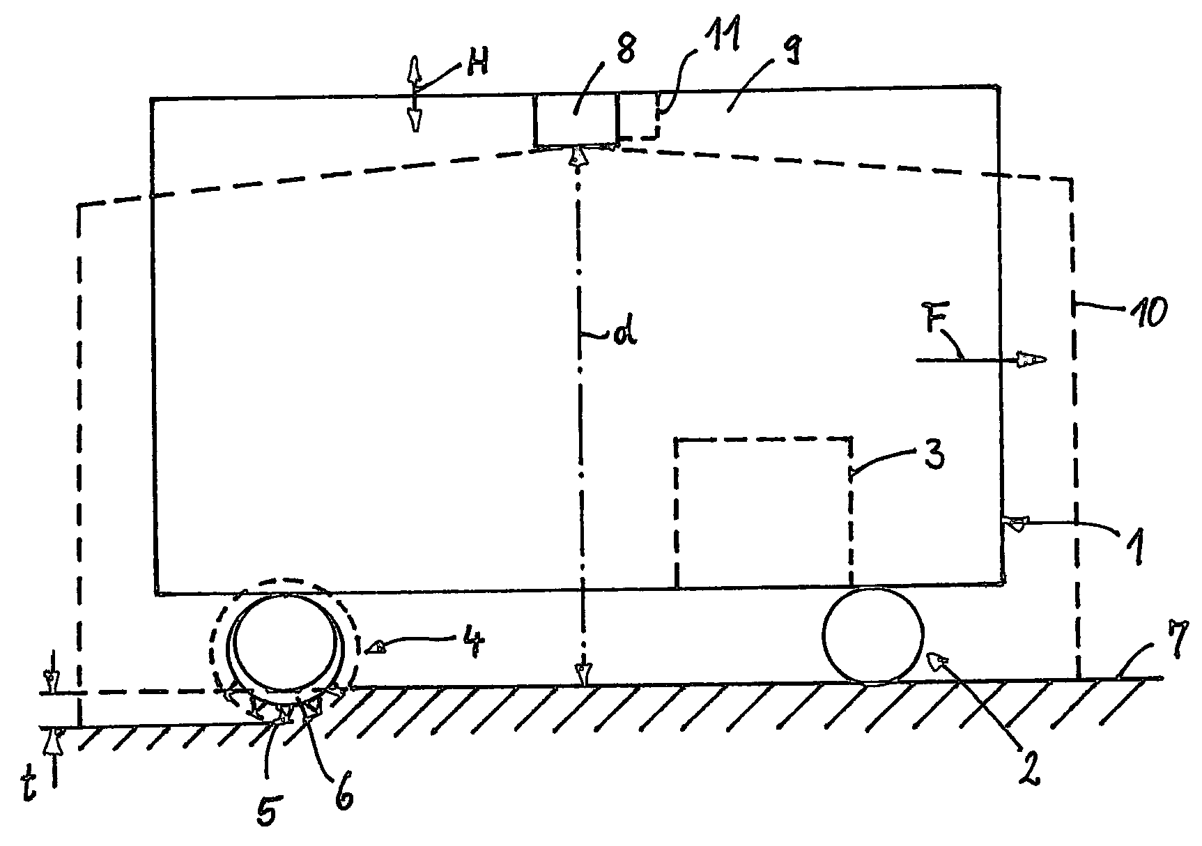
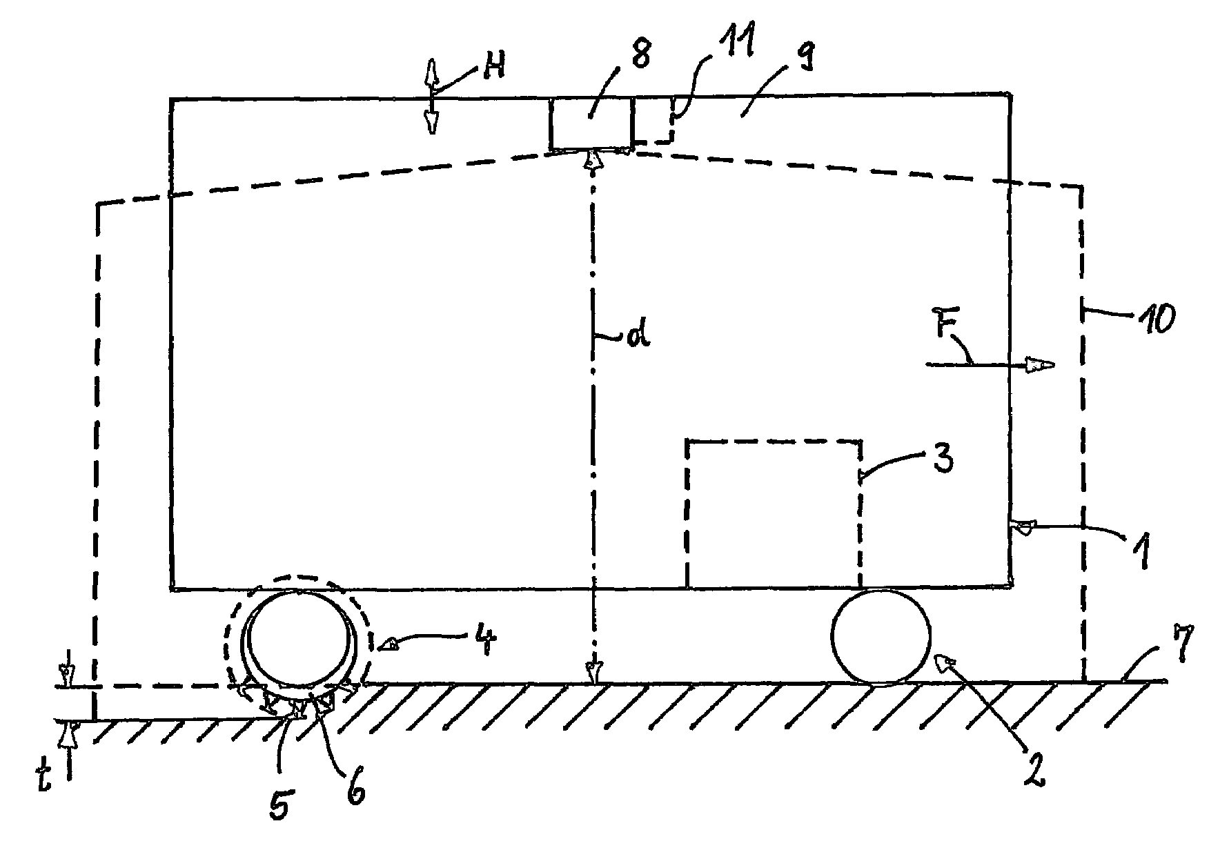
[0010]The machine shown for milling traffic areas comprises a chassis 1 which is arranged in a vertically adjustable manner relative to a travelling mechanism 2 which can be driven via a drive unit 3, for instance a diesel engine, installed in the chassis 1. A milling mechanism 4, which can likewise be driven via the drive unit 3 and comprises a milling drum 6 fitted with milling bits 5, is attached below and to the chassis 1.

[0011]The height of the chassis 1 relative to a traffic area 7 to be milled is measured via a laser scanner 8. The laser scanner 8 is located in the top centre side-wall region of the chassis 1 on a side wall 9 thereof and is attached with its scanning plane essentially parallel to the side wall 9. Laser scanners normally have an angular scanning range of about 180°, so that a defined hazard region 10 which is located in front of the side wall 9 of the chassis 1 is scanned by the laser scanner 8. The laser scanner 8 therefore firstly scans the distance d from t...


PUM


Abstract

The invention relates to a machine for milling traffic areas. The machine has a vertically adjustable chassis which carries a steerable traveling mechanism and a drive unit for moving the machine and for driving a milling mechanism coupled to the drive unit. A laser scanner is attached to at least on one side of the chassis. With the laser scanner, the height relative to the surface of a traffic area to be milled can be measured and the chassis can be set vertically in accordance with the measured values relative to the surface of the traffic area to be milled. The laser scanner is attached in the center side-wall region of the chassis. The scanning plane of the laser scanner is essentially parallel to the side-wall region of the chassis and at a height which permits monitoring of a hazard region which extends at least over the side length of the machine. The laser scanner produces a trigger signal if a disturbance occurs in the scanning plane.

Description

FIELD OF THE INVENTION[0001]The invention relates to a machine for milling traffic areas as roads or the like for instance to remove a defective layer to be replaced by subsequent paving.BACKGROUND OF THE INVENTION[0002]WO 93 / 08003 discloses a machine for milling floor areas inside a building for the purpose of leveling, in which machine a device for detecting the height of the floor is provided, this detecting device comprising a laser receiver on the machine, and this laser receiver evaluates an external laser beam which represents the reference height and replaces a reference cord which is otherwise used. According to said document, the height of the rear wheels is adjusted and thus the milling depth is kept at an intended level.[0003]Furthermore, German Patent No. DE 196 32 456 C1 discloses a self-propelled, i.e. driverless, machine for skimming artificial grounds, such as sand tennis courts or the like, in which, for determining the position in connection with markings located ...

Claims


Application Information

Patent Timeline
Patent Type & Authority Patents(United States)
IPC IPC(8): E01C23/088
CPCE01C19/006E01C23/088
Inventor LEMKE, BERND
Owner ABG ALLG BAUMASCHINEN GMBH
Why Eureka
Try Eureka