Apparatus and method for connecting a conduit to a hollow organ

a technology of conduit and hollow organ, which is applied in the field of apparatus and method for connecting a conduit to a hollow organ, can solve the problems of substantial blood loss and inevitable, and achieve the effect of reducing the likelihood of tissue damage or other complications and facilitating procedures

Inactive Publication Date: 2009-03-31
CORREX
View PDF42 Cites 54 Cited by
  • Summary
  • Abstract
  • Description
  • Claims
  • Application Information

AI Technical Summary

Benefits of technology

[0017]As described earlier, the surgeon conventionally uses a cork borer to cut a tissue plug from the ventricle wall. Once the tissue plug is removed, the surgeon must attempt to occlude the resulting hole, such as with a finger, a balloon or some other occlusion means, until the connector conduit is inserted. Despite attempts to occlude the resulting hole, substantial blood loss is inevitable. Cardiopulmonary bypass is used to reduce blood loss.
[0057]The invention facilitates procedures using an integral device in which the various steps are preformed in a coordinated, i.e. sequenced manner. This renders the procedure simple and safe and reduces the likelihood of tissue damage or other complications. Other features and advantages of the invention will be apparent from the detailed description and from the claims.

Problems solved by technology

Despite attempts to occlude the resulting hole, substantial blood loss is inevitable.

Method used


Image

  • Apparatus and method for connecting a conduit to a hollow organ
  • Apparatus and method for connecting a conduit to a hollow organ
  • Apparatus and method for connecting a conduit to a hollow organ

Examples


Embodiment Construction

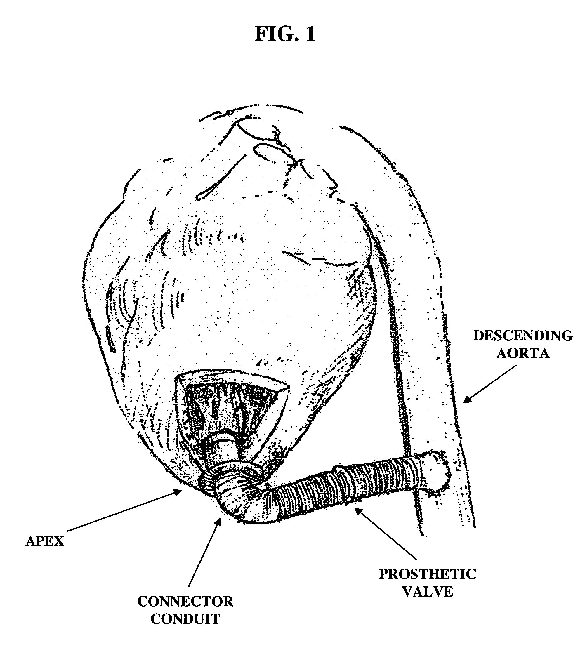
[0095]FIG. 1 is an illustration of an apicoaortic conduit, which extends from the apex of the left ventricle to the descending aorta with a prosthetic valve positioned within the conduit. The preferred embodiment of the present invention includes aspects of the connector conduit and an applicator used to implant the connector conduit.

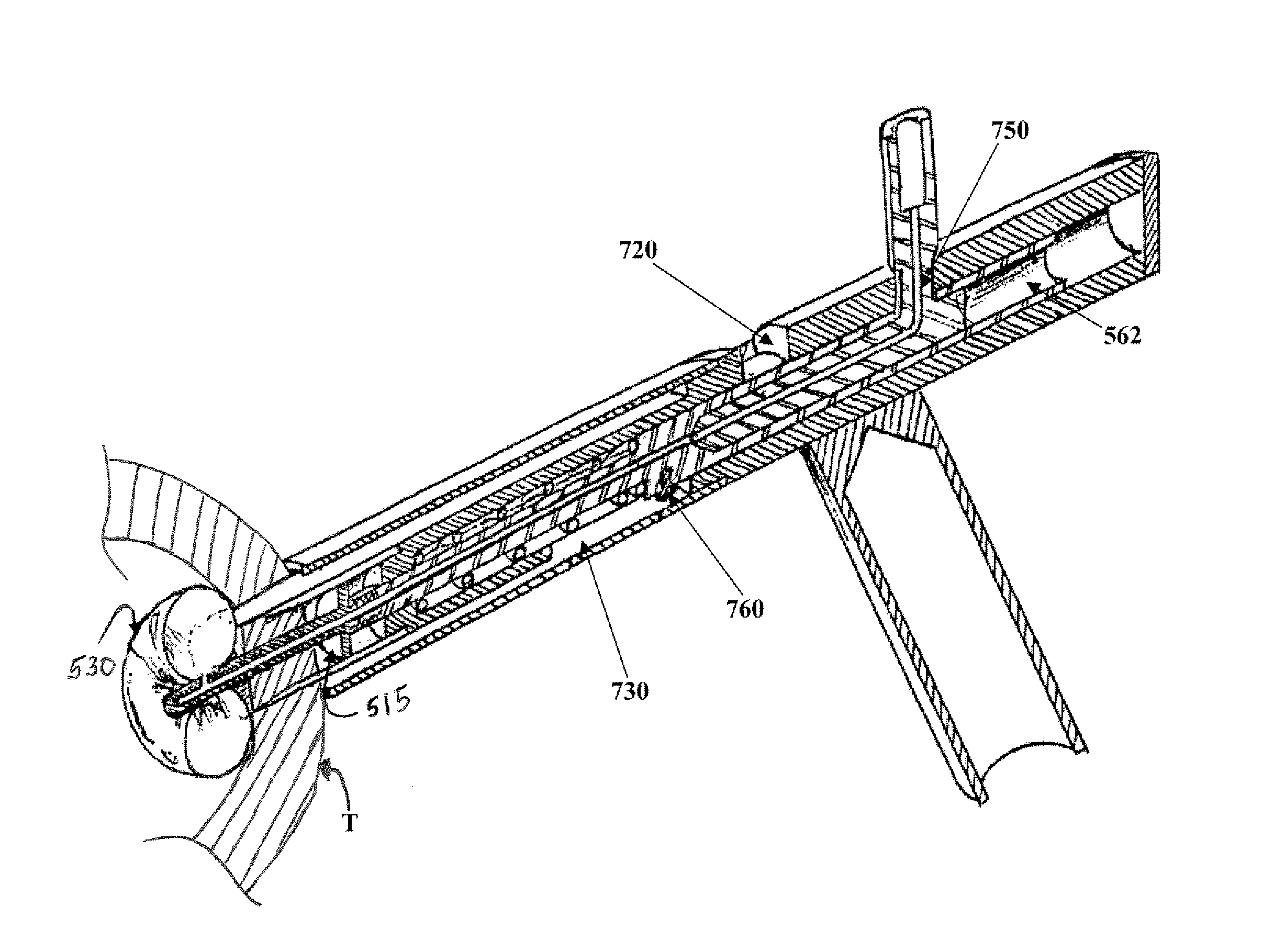
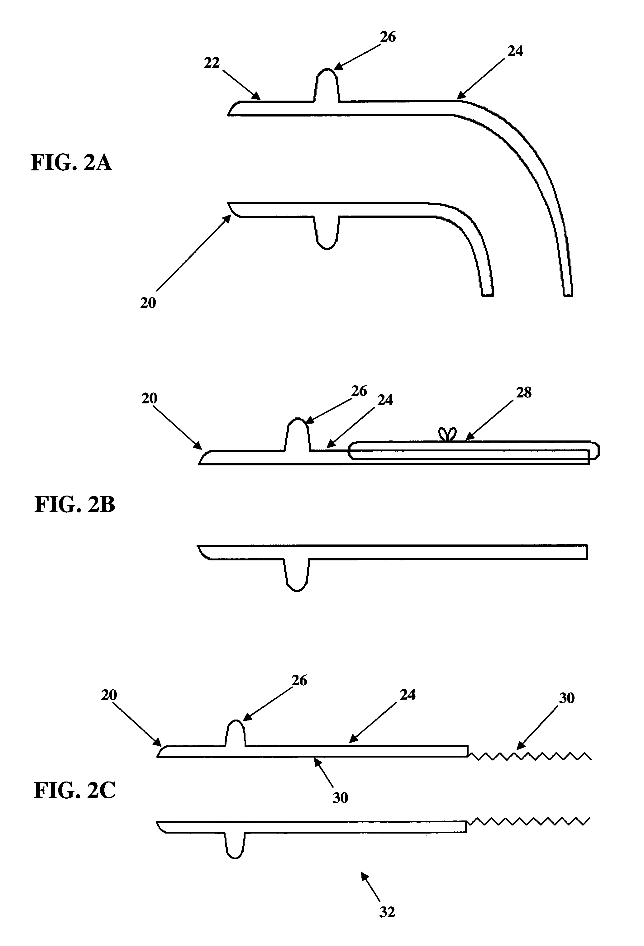
[0096]The connector-conduit with applicator of the present invention is best described as consisting of five major parts: a connector-conduit, a retractor, hole forming device such as a coring element, a pushing component, and a handle. A fabric material pleated conduit of a type common and well known in the field is permanently fixed to the inner surface of a rigid connector to form the connector-conduit. The conduit extends from the forward edge of the connector and continues beyond the connector, as a flexible portion, for some distance.

[0097]The connector-conduit includes a rigid portion defined by an internal support structure made of a suitably fl...


PUM


Abstract

An apparatus and method for connecting a first conduit to the heart without the need for cardiopulmonary bypass. The first conduit may then be attached to a second conduit that has a prosthetic device interposed. The second conduit may be connected to the aorta prior to the first conduit being attached to the heart. The prosthetic device may be a prosthetic valve or a pump, for example. The apparatus of the present invention includes an implantable connector with first conduit component, a retractor expansion component, a coring component, and a pushing component. The retractor expansion component is slideably coupled to the coring component. The retractor expansion component serves to seat against and separate the inside apical wall of the left ventricle so that the coring component may cut cleanly through the myocardium to form a tissue plug without leaving any hanging attachments to the inside walls. By remaining seated against the inside wall, the retractor expansion component follows the tissue plug into the coring component. The surgeon applies force and rotary motion to the pushing component sufficient to cut the tissue plug and implant the prosthetic component.

Description

RELATED APPLICATIONS[0001]This application claims priority of U.S. Provisional Application Ser. Nos. 60 / 555,308, filed Mar. 23, 2004; 60 / 635,652 filed on Dec. 14, 2004 and 60 / 636,449 filed on Dec. 15, 2004.BACKGROUND OF THE INVENTION[0002]1. Field of the Invention[0003]The present invention relates to an apparatus and method for connecting a conduit to a hollow organ, and more particularly, to a surgical device connectable to the apex of a heart.[0004]2. Description of the Related Art[0005]As the average age of the United States population increases, so do the instances of aortic stenosis. An alternative approach to the conventional surgical replacement of the stenotic aortic valve involves the use of an apicoaortic conduit. In this approach, the native aortic valve is not removed, and a prosthetic valve is implanted in a parallel flow arrangement. A connection conduit (or tube) connects the apex of the heart to the descending aorta. Somewhere along this conduit, the prosthetic valv...

Claims


Application Information

Patent Timeline
Patent Type & Authority Patents(United States)
IPC IPC(8): A61B17/11A61B17/00A61B17/02A61B17/32A61F2/06
CPCA61B17/0218A61B17/11A61B17/32053A61F2/064A61B17/320016A61B2017/00247A61B2017/00252A61B2017/00557A61B2017/0237A61B2017/1107A61B2018/00392
Inventor BEANE, RICHARD M.BROWN, JOHN W.CRUNKLETON, JAMES ALANGAMMIE, JAMES S.SMITH, JR., JOSEPH L.
Owner CORREX
Why Eureka
Try Eureka