Multi-band filter module and method of fabricating the same

a filter module and multi-band technology, applied in the field of multi-band filter module and fabricating the same, can solve the problems of product yield degradation, and achieve the effect of reducing coupling phenomenon and improving device yield

Active Publication Date: 2009-03-31
SAMSUNG ELECTRONICS CO LTD
View PDF9 Cites 17 Cited by
  • Summary
  • Abstract
  • Description
  • Claims
  • Application Information

AI Technical Summary

Benefits of technology

[0011]The present invention has been developed in order to address the above drawbacks and other problems associated with the conventional arrangement of the filters in a multi-band filter module. An aspect of the present invention is to provide a multi-band filter module and a method of fabricating the same, which can reduce a coupling phenomenon and improve the yield of a device by distributing output pads closely arranged on one substrate.
[0012]Another aspect of the present invention is to provide a multi-band filter module and a method of fabricating the same, which can reduce the size of an integrated filter and increase convenience in manufacturing the filter to reduce its manufacturing cost.

Problems solved by technology

Also, due to the coupling phenomenon, the related art filter module 100 cannot perform an accurate filtering by frequency bands, and thus a yield of the product is degraded.

Method used


Image

  • Multi-band filter module and method of fabricating the same
  • Multi-band filter module and method of fabricating the same
  • Multi-band filter module and method of fabricating the same

Examples


Embodiment Construction

[0033]Certain exemplary embodiments of the present invention will be described in greater detail with reference to the accompanying drawings.

[0034]In the following description, the same drawing reference numerals are used for the same elements even in different drawings. The matters defined in the description such as a detailed construction and elements are nothing but the ones provided to assist in a comprehensive understanding of the invention. Thus, it is apparent that the present invention can be carried out without those defined matters. Also, well-known functions or constructions are not described in detail since they would obscure the invention in unnecessary detail.

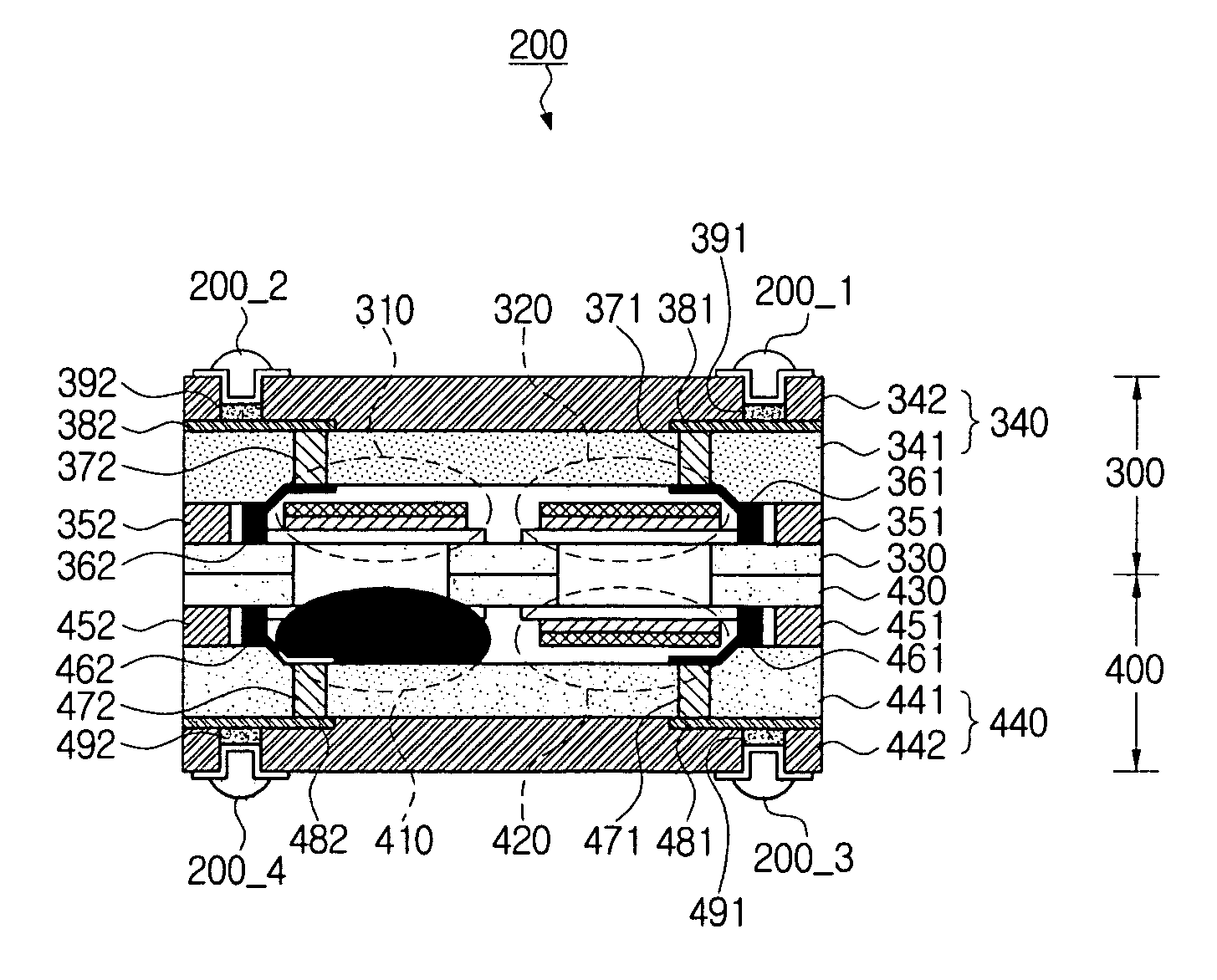
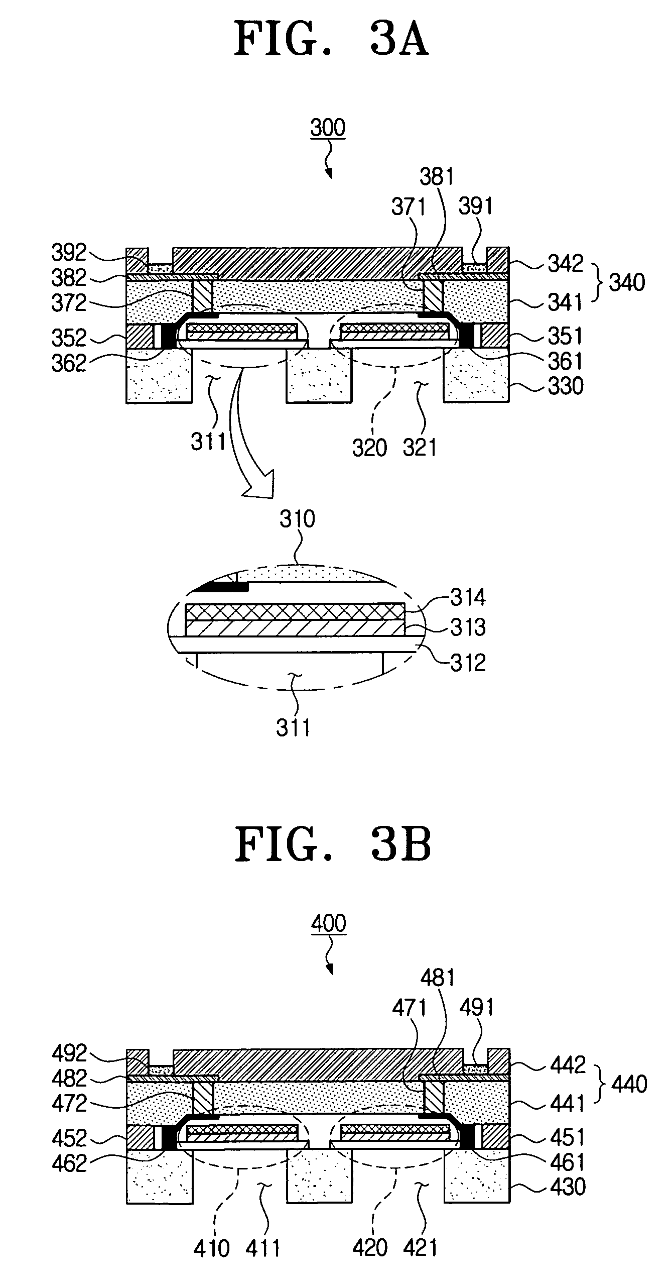
[0035]FIG. 2 is a vertical longitudinal sectional view schematically illustrating a filter module having a multi-band function according to an exemplary embodiment of the present invention. FIGS. 3A and 3B are vertical longitudinal sectional view illustrating the first filter module and the second filter module sh...


PUM

PropertyMeasurementUnit
frequency bandaaaaaaaaaa
frequencyaaaaaaaaaa
piezoelectricaaaaaaaaaa

Abstract

A multi-band filter module and a method of fabricating the same are disclosed. At least one upper filter is deposited on an upper surface of a first substrate. The first packaging substrate packages the upper filter deposited on the first substrate. At least one lower filter is deposited on an upper surface of the second substrate. The second packaging substrate packages the lower filter deposited on the second substrate. The lower surface of the first substrate is joined to a lower surface of the second substrate to face each other.

Description

CROSS-REFERENCE TO RELATED APPLICATION[0001]This application claims priority under 35 U.S.C. § 119 from Korean Patent Application No. 10-2006-0011154, filed on Feb. 6, 2006, in the Korean Intellectual Property Office, the entire contents of which are incorporated herein by reference.BACKGROUND OF THE INVENTION[0002]1. Field of the Invention[0003]Apparatuses and methods consistent with the invention relate to a multi-band filter module and fabricating the same, and more particularly, to a multi-band filter module that provides a multi-band function through at least two packaged filters, and fabricating the same.[0004]2. Description of the Related Art[0005]Global System for Mobile Communications (GSM) is a communication technology whereby persons can conveniently use mobile communication devices in many countries across the world, without requiring international roaming. The GSM has been widely spread around Europe.[0006]The GSM is briefly divided into bands of GSM 850, GSM 900, GSM 1...

Claims


Application Information

Patent Timeline
Patent Type & Authority Patents(United States)
IPC IPC(8): H03H9/70H03H3/02
CPCH03H3/04H03H9/105H03H9/587H03H9/703Y10T29/42H01L2924/0002H03H2250/00H01L2924/00B23Q16/021
Inventor PARK, YUN-KWONSONG, IN-SANGKIM, CHUL-SOONAM, KUANG-WOO
Owner SAMSUNG ELECTRONICS CO LTD
Why Eureka
Try Eureka