Autocapture pacing/sensing configuration

a technology of autocapture and sensing, which is applied in the direction of electrotherapy, heart stimulators, therapy, etc., can solve the problems of difficult detection of evoked depolarization or “capture verification” using the same electrode for pacing and sensing, waste of capture threshold of pacemaker's limited power supply, etc., and achieve enhanced detection of evoked responses and shorten afterpotentials

Inactive Publication Date: 2009-03-31
CARDIAC PACEMAKERS INC
View PDF13 Cites 11 Cited by
  • Summary
  • Abstract
  • Description
  • Claims
  • Application Information

AI Technical Summary

Benefits of technology

[0015]The present invention may be utilized with unipolar or bipolar atrial and ventricular pacing and sensing leads, and which may attenuate and shorten afterpotentials and thereby enhance the detection of an evoked response in a preselected chamber of the heart. When used with atrial autocapture verification or evoked response detection, a bipolar atrial lead is preferred and the ventricular lead may be either unipolar or bipolar. Likewise, when used with ventricular autocapture, the ventricular lead is preferably bipolar and the atrial lead can be either unipolar or bipolar. The present invention may utilize the pacing electrodes of a bipolar atrial lead and bipolar ventricular lead to both pace and sense an evoked response in a preselected chamber of the heart. The pacing system of the present invention may reduce the required blanking period and attenuate afterpotential developed at the pacing electrodes.

Problems solved by technology

The ability of a pacemaker to detect capture is desirable in that delivering stimulation pulses having energy far in excess of the patient's capture threshold is wasteful of the pacemaker's limited power supply.
While the conventional pacing circuit is generally effective in delivering stimulus pulses to a selected chamber of the heart, it has been found that the detection of evoked depolarization or “capture verification” using the same electrode for pacing and sensing is difficult due to polarization voltages or “afterpotentials” which develop at the tissue / electrode interface following the application of the stimulation pulses.

Method used


Image

  • Autocapture pacing/sensing configuration
  • Autocapture pacing/sensing configuration
  • Autocapture pacing/sensing configuration

Examples


Embodiment Construction

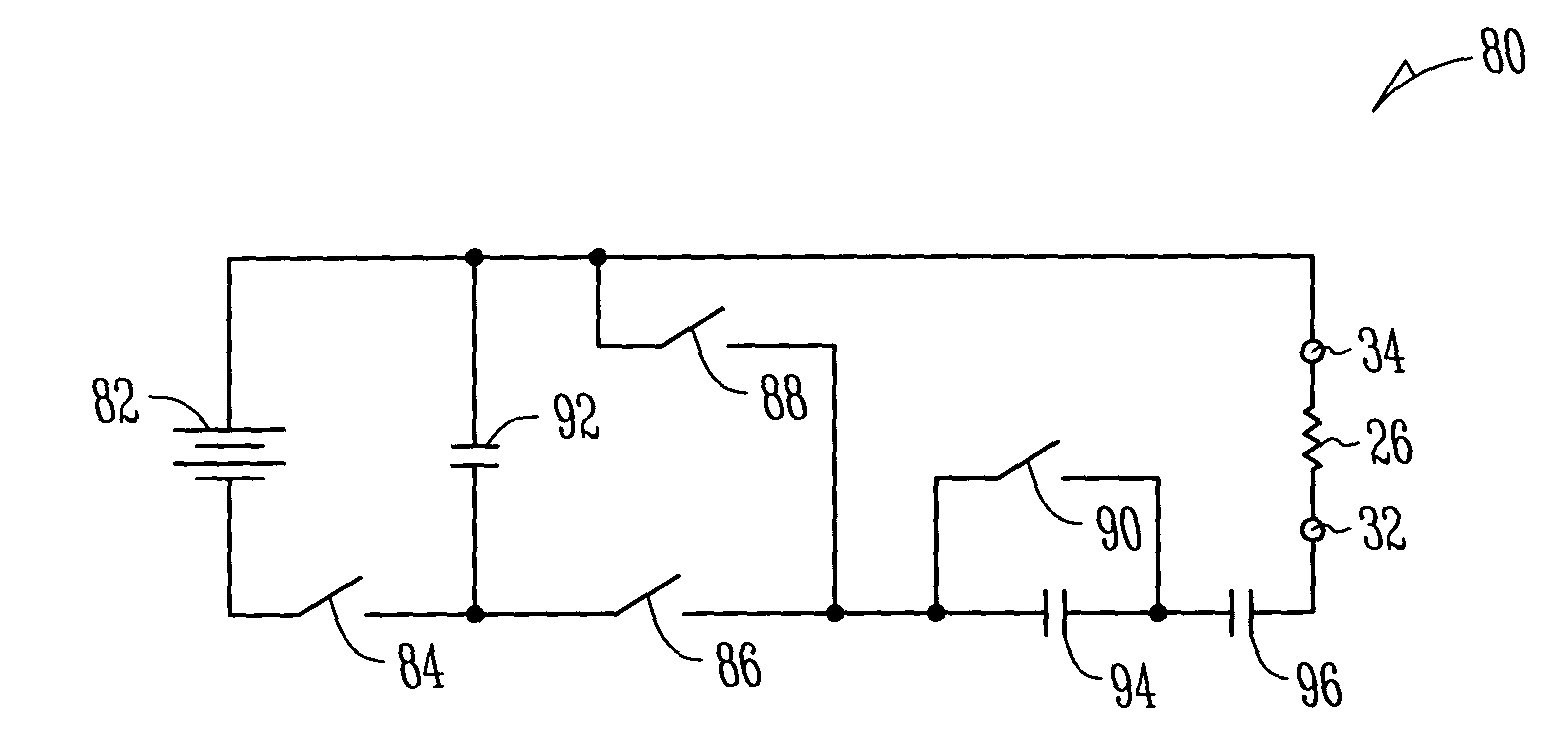
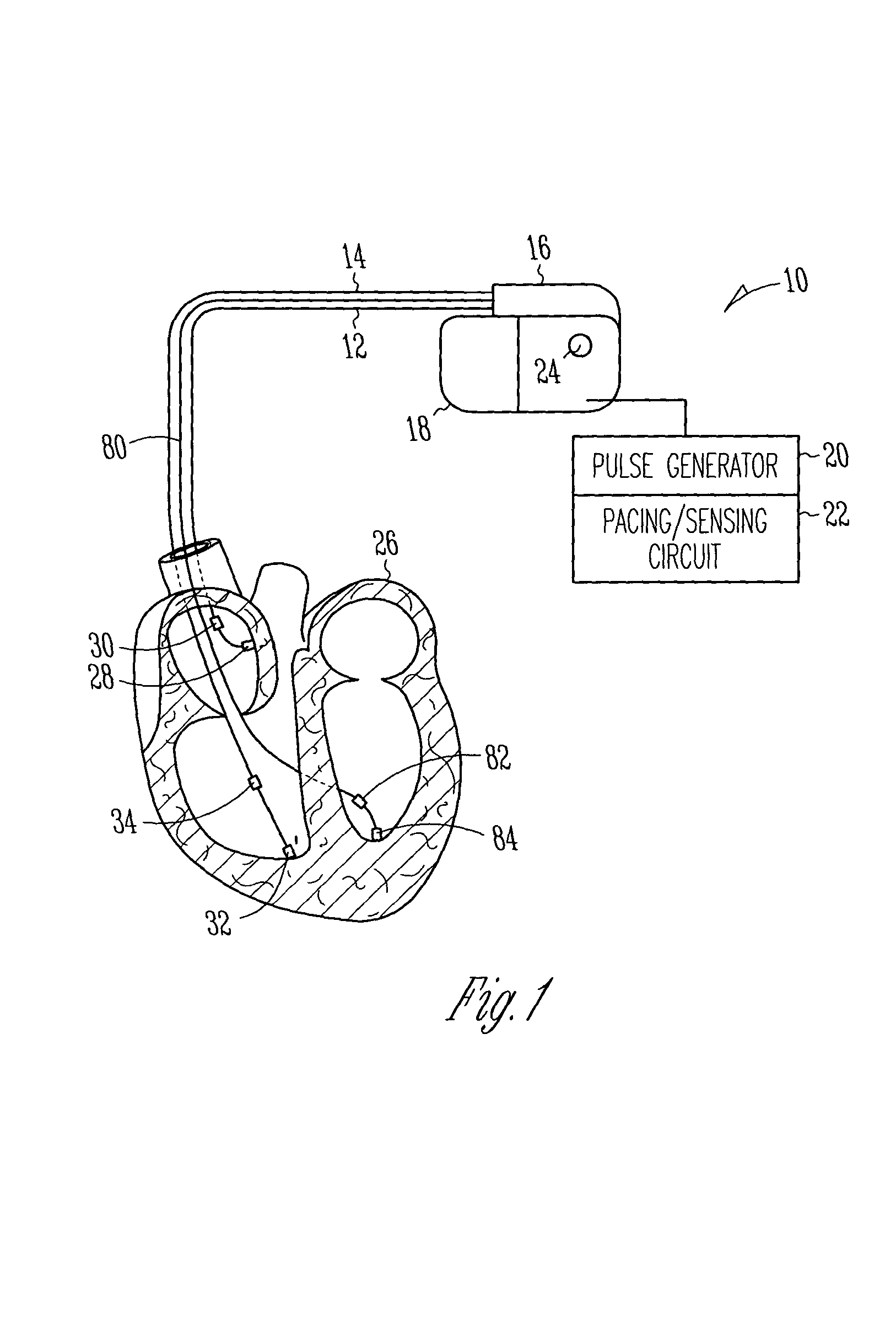
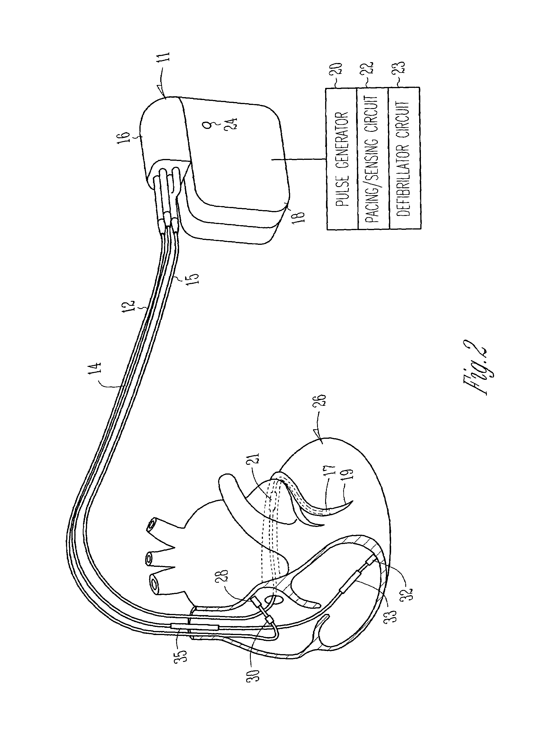
[0036]FIG. 1 illustrates a cardiac pacing system in accordance with the present invention. The cardiac pacing system includes a cardiac pacer 10, an atrial lead 12 and a right ventricular lead 14. In addition or as an alternative to right ventricular lead 14, the cardiac pacing system may include a left ventricular lead 80. The cardiac pacer 10 includes a header 16 and can 18, wherein a pulse generator 20 including pacing and sensing circuits 22 are contained therein. An indifferent electrode 24 of suitable known construction is positioned on the can 18 such that the indifferent electrode 24 is electrically isolated from the can 18 and is electrically coupled to the sensing circuit 22. Atrial lead 12, right ventricular lead 14 and left ventricular lead 80 are engaged to header 16 and may be electrically coupled to the pulse generator 20 and pacing and sensing circuits 22 in a known suitable fashion. The atrial lead 12 is positioned in the atrium of the heart 26, wherein the atrial l...


PUM


Abstract

A cardiac electrical stimulation system that enhances the ability of the system to automatically detect whether an electrical stimulus results in heart capture or contraction. The cardiac electrical stimulation system may be utilized, for example, as a cardiac pacer or as a cardioverter defibrillator. The cardiac electrical stimulation system includes an electrical stimulation circuit that attenuates polarization voltages or “afterpotential” which develop at the heart tissue/electrode interface following the delivery of a stimulus to the heart tissue, which thereby allows the stimulation electrodes to be utilized to sense an evoked response to the electrical stimulus. The cardiac electrical stimulation system utilizes the stimulation electrodes to sense an evoked response, thereby eliminating the necessity for an indifferent electrode to sense an evoked response. The present invention allows accurate detection of an evoked response of the heart, to thereby determine whether each electrical stimulus results in capture.

Description

[0001]The present application is a Continuation-In-Part of applications Ser. No. 09 / 206,329, filed on Dec. 8, 1998, issued as U.S. Pat. No. 7,092.756, and entitled AUTOCAPTURE PACING / SENSING CONFIGUIRATION and Ser. No. 09 / 206,896, filed on Dec. 8, 1998, issued as U.S. Pat. No. 6,169.921, and entitled AUTOCAPTURE DETERMINATION FOR AN IMPLANTABLE CARDIOVERTER DEFIBRILLATOR.I. FIELD OF THE INVENTION[0002]The present invention relates to cardiac rhythm management devices and, more particularly, to an apparatus and method that automatically detects whether or not an electrical stimulus results in heart capture or contraction.II. BACKGROUND OF THE INVENTION[0003]Cardiac pacers have enjoyed widespread use and popularity through time as a means for supplanting some or all of an abnormal heart's natural pacing functions. The various heart abnormalities remedied by pacemakers include total or partial heart block, arrhythmias, myocardial infarctions, congestive heart failure, congenital heart ...

Claims


Application Information

Patent Timeline
Patent Type & Authority Patents(United States)
IPC IPC(8): A61N1/368A61N1/37
CPCA61N1/3712A61N1/3716
Inventor ZHANG, GENGKIM, JUNGKUKZHU, QINGSHENG
Owner CARDIAC PACEMAKERS INC
Why Eureka
Try Eureka