Anchor attachment for a roof panel rib

a technology for fixing brackets and roof panels, which is applied in the direction of snow traps, rod connections, manufacturing tools, etc., can solve the problems of disrupting the mechanism of the thin-walled roof panel rib is typically unable to sustain the clamping force required, and the roof panel rib is unable to readily come apart or go back together for roof panel replacement, so as to avoid damage to the head and the neck by threads

Inactive Publication Date: 2009-04-07
SHOWALTER GREGORY
View PDF7 Cites 63 Cited by
  • Summary
  • Abstract
  • Description
  • Claims
  • Application Information

AI Technical Summary

Benefits of technology

[0009]To prevent a roof panel rib from collapsing or suffering severe deformation under clamping force of the setscrews, a rib bar typically shaped to functionally match the roof panel rib is inserted within the roof panel rib as a brace. When the anchor setscrews tighten against the roof panel rib, the panel rib sides are sandwiched between the rib bar and the setscrews. The bar sustains the clamping force thereby maintaining the shape of the roof panel rib.
[0010]Typically, a roof panel rib comprises a head supported on a thinner neck, matching the shape of the roof panel rib. To prevent the anchor from lifting off the roof panel rib, the setscrews are located on the anchor sides low in the anchor channel, sufficiently apart from the anchor top so that the roof panel rib head can be received between the setscrews and the anchor top. The setscrews then tighten into the roof panel rib at the roof panel rib neck where the neck meets the head. When the setscrews are threaded into the channel under the head, the anchor is prevented from lifting off the roof panel rib, independent of the frictional clamping force that might be applied by the setscrews against the neck. To avoid damage to the head and the neck by threads of the setscrew, the screw threads end intermediate the setscrew, leaving a smooth rod terminating on a setscrew abutment surface. That is, with the setscrew engaging the roof rib with a portion of the head portion and a portion of the neck portion extending outward toward the setscrew, setscrew threads continuing to the setscrew end as in a traditional set screw would cut into and damage the roof rib. It is therefore necessary to end the threads well short of the setscrew abutment surface. Also, for the same reason that the setscrew is not engaging a flat surface, it is necessary in order to not cut into and damage the roof rib that the end of the set screw not present corners that would likely cut into the roof rib but rather end in a curved surface the tapers and blends a curved abutment surface smoothly without discontinuity into the smooth, unthreaded rod portion.

Problems solved by technology

A thin-walled roof panel rib is typically unable to sustain the clamping force required to keep the anchor from sliding on the roof panel rib without permanently deforming the roof panel rib.
Once deformed, the roof panel rib is unable to readily come apart or go back together for roof panel replacement.
The deformation disrupts the mechanism of the panel rib and is aesthetically displeasing.

Method used


Image

  • Anchor attachment for a roof panel rib
  • Anchor attachment for a roof panel rib
  • Anchor attachment for a roof panel rib

Examples


Embodiment Construction

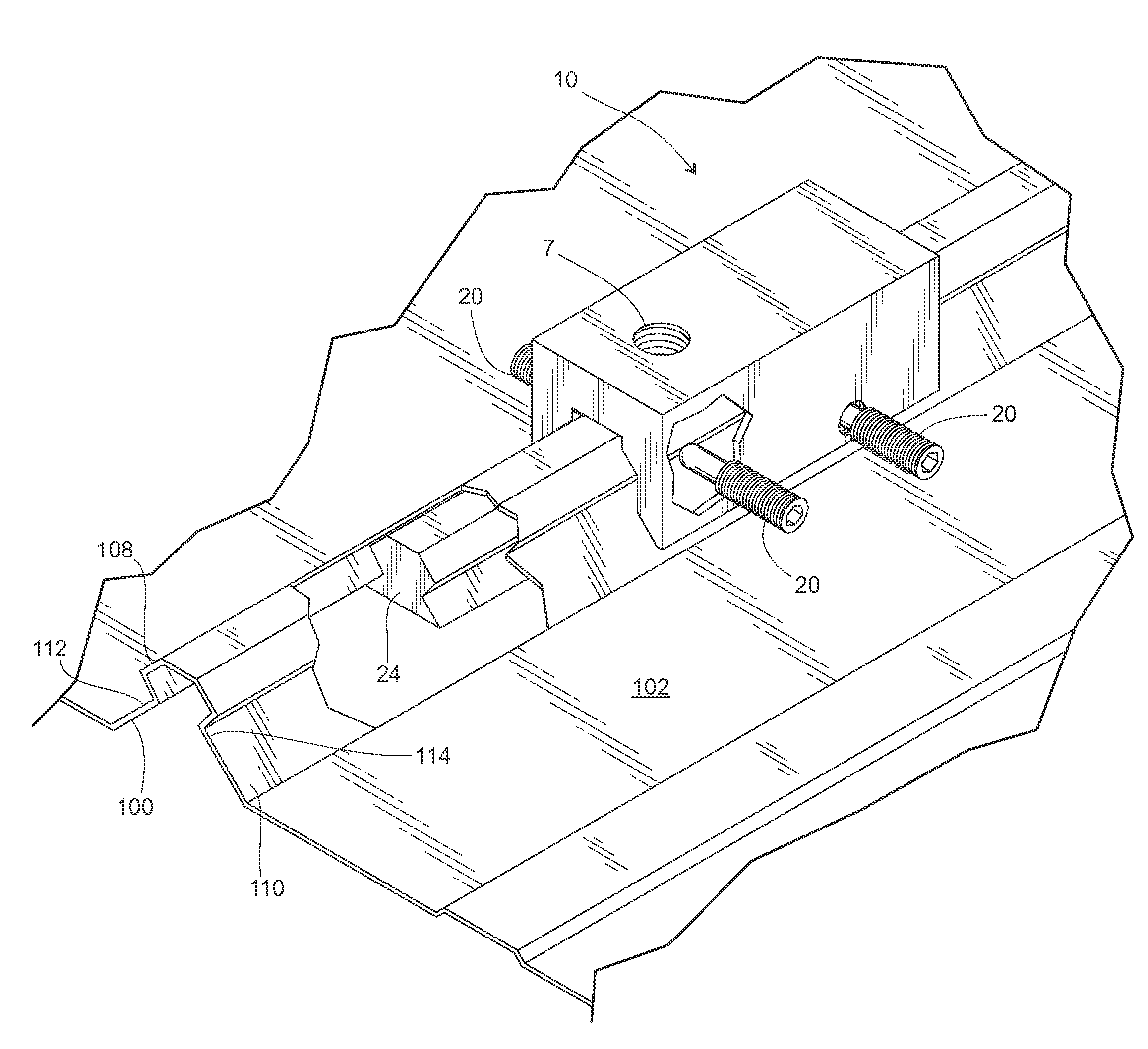
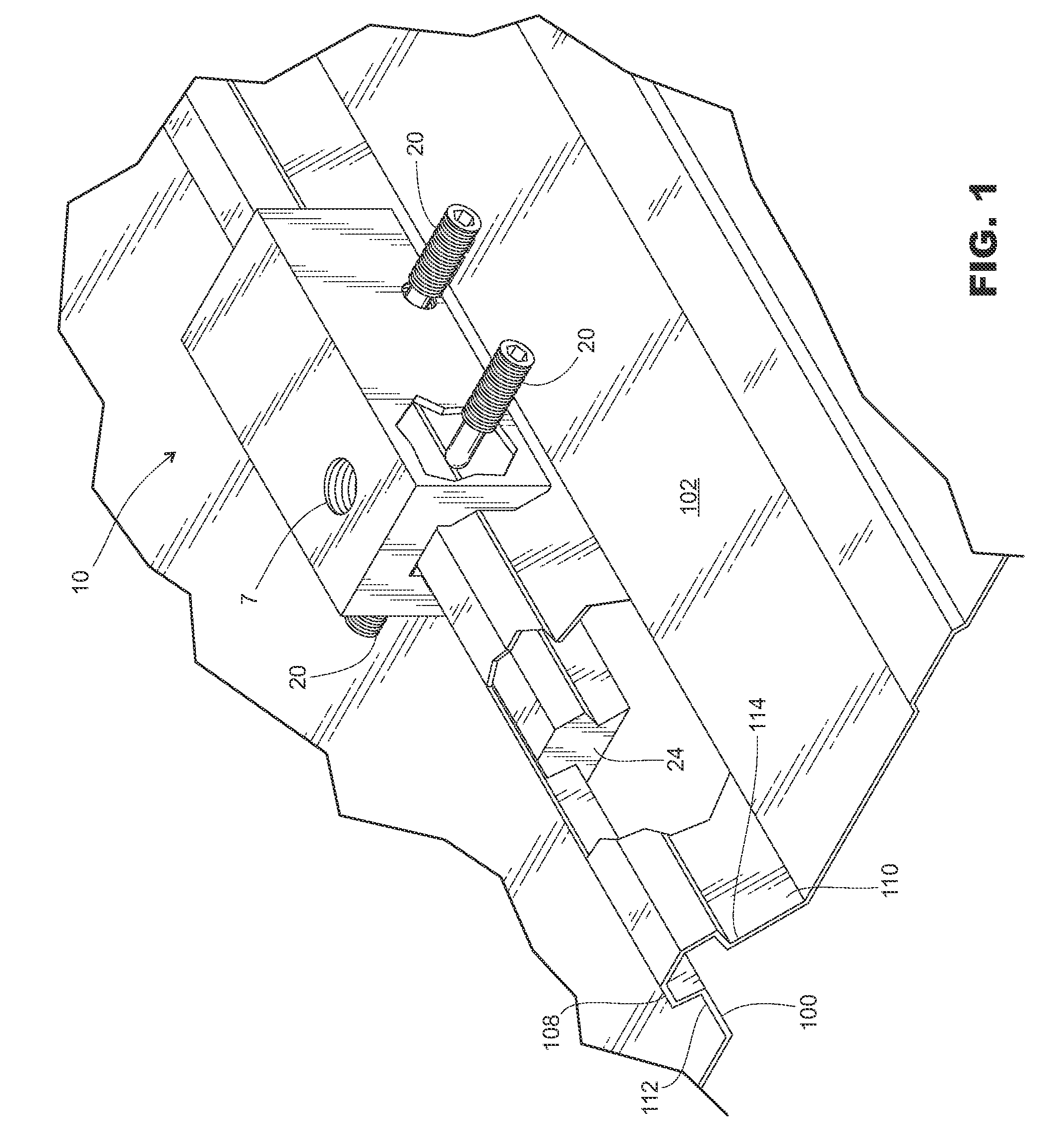
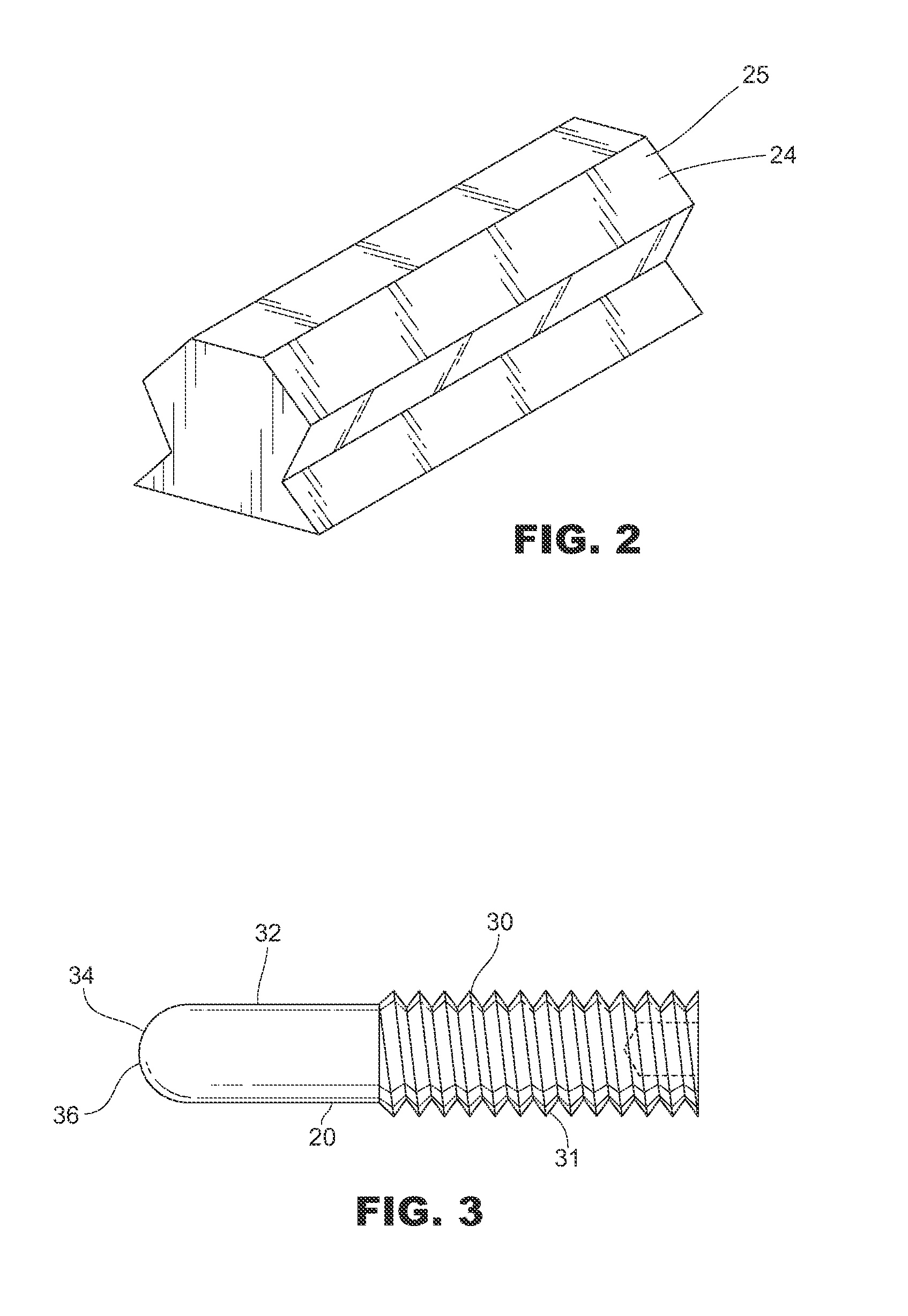
[0018]A roof panel rib anchor 10 for attachment to a roof panel rib 100 of a roof panel 102 or panels comprises first and second opposing anchor sides 12 and 14 depending from an anchor top 16 forming a channel 18 within and sized to receive a roof panel rib in the channel. A fastener spaced apart from the anchor top 16 on a first anchor side 12 extends into the channel 18 directed toward the other anchor side 14 at least partially closes the channel 18. Typically, the fastener comprises a threaded setscrew 20 and more typically a plurality of threaded setscrews penetrating at least a first anchor side 12 through matching threaded holes 22. When tightened into the channel 18, the setscrews 20 releasably clamp the roof panel rib 100 securely between the setscrew 20 and the second anchor side 14 with clamping force sufficient to prevent the anchor from sliding on the roof panel rib. When the setscrews are on both anchor sides, they may be arranged in opposing pairs, with a setscrew fr...


PUM


Abstract

A roof anchor with a channel fits over a roof panel rib typically having a rib head supported by a narrower rib neck. Setscrews on the anchor side thread through matching threaded holes in anchor sides and into the channel, sandwiching a roof panel rib therebetween when it is received into the channel. To prevent the anchor from lifting off the roof panel rib, the setscrews are located on the anchor sides low in the anchor channel engaging the roof panel rib at the narrow rib neck such that the roof panel rib head can be received between the setscrews and the anchor top. A rib bar typically shaped to functionally match the roof panel rib may be inserted within the roof panel rib as a brace to prevent a roof panel rib from collapsing under force of the setscrews.

Description

BACKGROUND[0001]1. Field of the Invention[0002]This invention relates to attachments for roof panels, and more specifically, to an anchor mountable to a roof panel rib, to which roof paraphernalia may be attached, and the unique setscrew that secures to the roof panel rib.[0003]2. Prior Art[0004]Metal roof panels are in common usage. With such usage, it is often an advantage to attach equipment to the roof panel. For example, snow guards that control snow and ice sliding on the roof, cable guy wires, walking platforms, piping, signage, brackets, etc. It is important that such attachments not penetrate the roof panel so leaks are not introduced.[0005]Metal roof panels are commonly joined with a raised portion on a first side overlapping a raised portion of an adjacent panel, together forming a roof panel rib raised above the general roof panels. In addition, some metal roof panels have an intermediate rib between the overlapping adjacent panel ribs. The panels are installed with the ...

Claims


Application Information

Patent Timeline
Patent Type & Authority Patents(United States)
IPC IPC(8): E04B1/38
CPCE04D13/10Y10T403/7062
Inventor SHOWALTER, GREGORY
Owner SHOWALTER GREGORY
Why Eureka
Try Eureka