

Image projection system with vibration compensation
a projection system and vibration compensation technology, applied in the field of optical image projection systems, can solve the problems of mechanical deformation of projection systems, acceleration and vibration of projection systems, adversely affecting projected images,
- Summary
- Abstract
- Description
- Claims
- Application Information
AI Technical Summary
Benefits of technology
Problems solved by technology
Method used
Image

Examples
Embodiment Construction
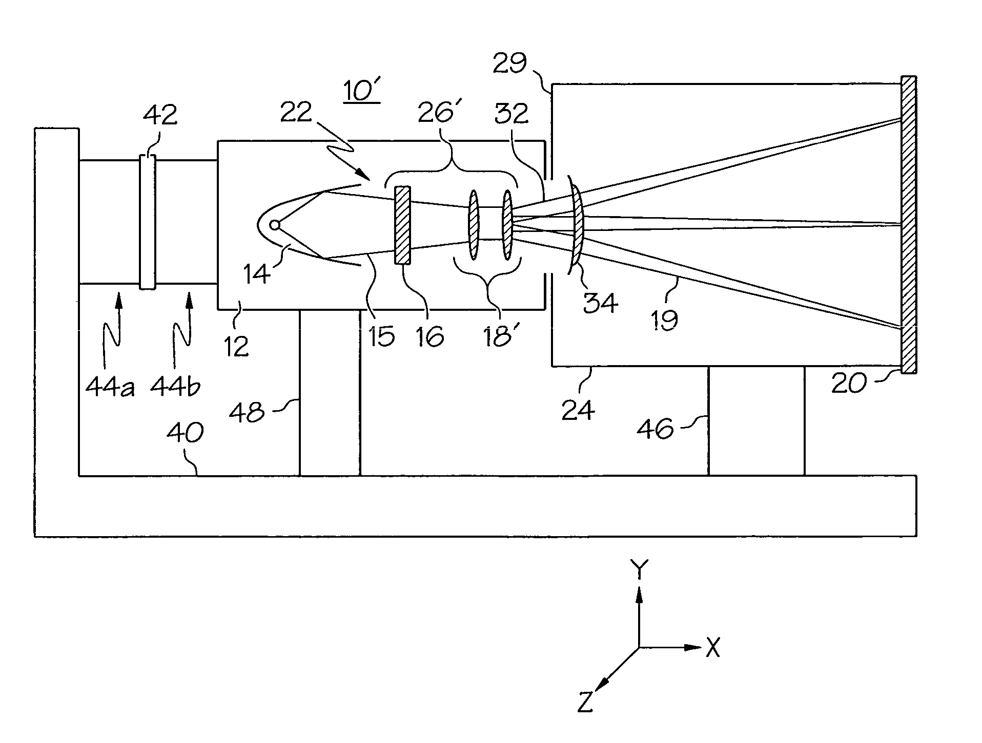
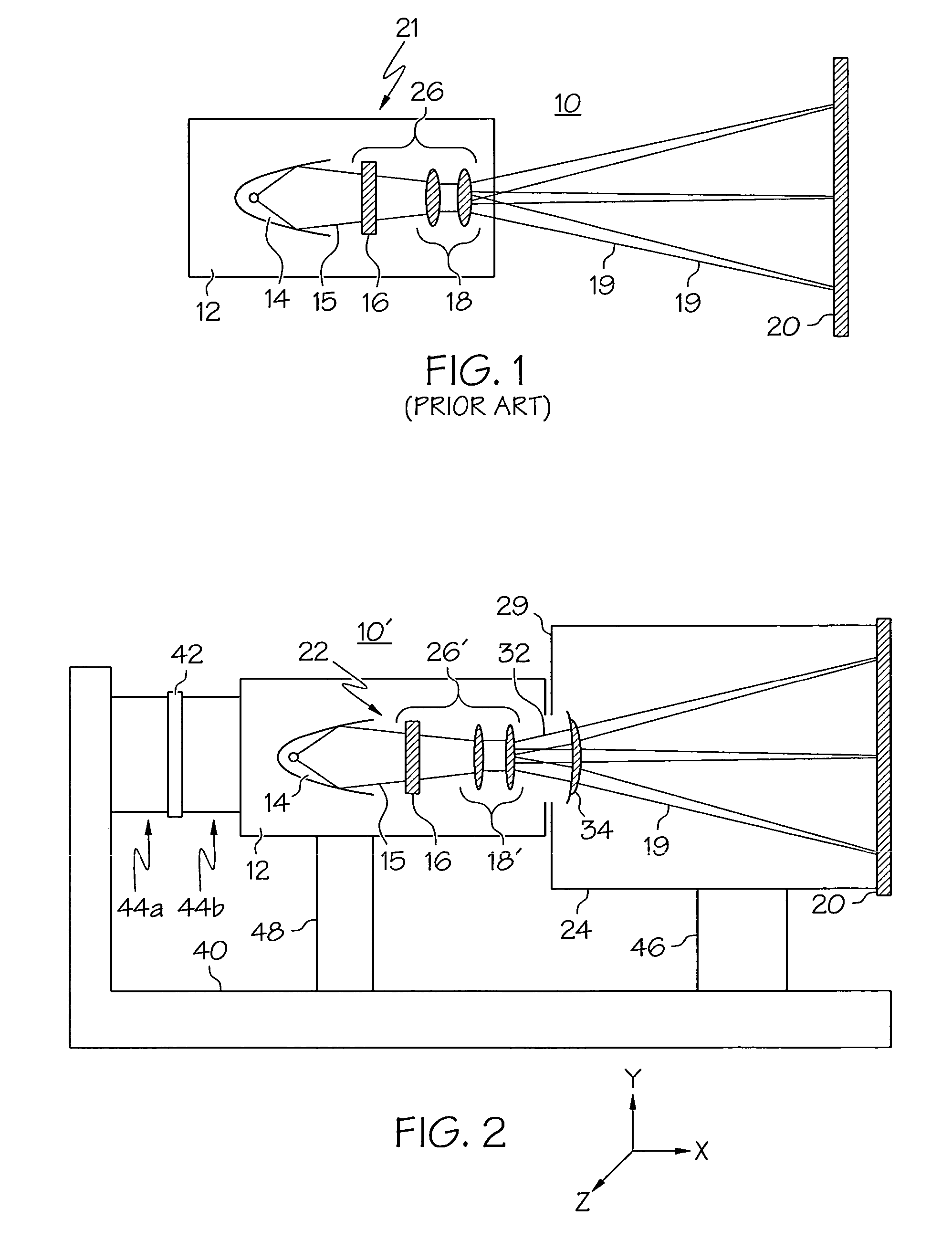
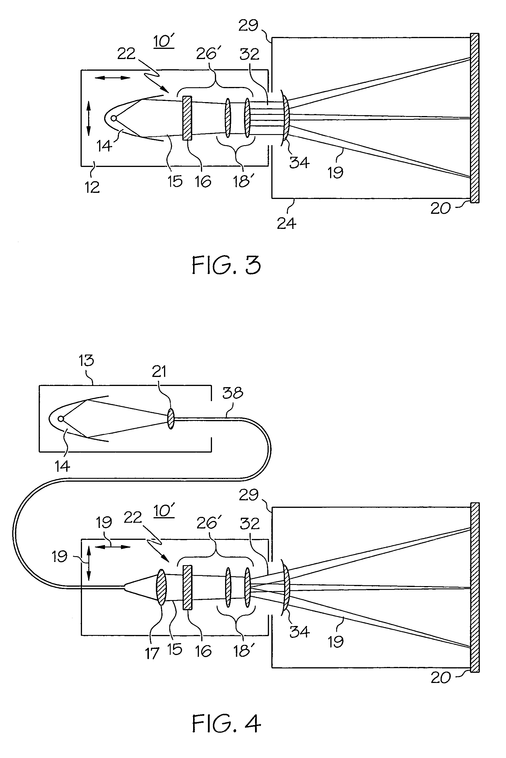
[0024]The following detailed description of the invention is merely exemplary in nature and is not intended to limit the invention or the application and uses of the invention. Furthermore, there is no intention to be bound by any theory presented in the preceding background of the invention or the following detailed description of the invention. Moreover, in the drawings, like reference numerals denote like elements throughout the several views. Several drawings in this description show side section views of optical projection systems. In an actual system constructed according to usual practice, additional mounts or brackets solidly attach each optical component to the housing or subassembly that encloses them. For convenience these mounts are not shown.
[0025]FIG. 1 illustrates a typical prior art projection display system 10. System 10 generally comprises a projector 21 having an illuminating element 14 and projection optics 26. Illuminating element 14 generates a light beam 15 sh...
PUM
 Abstract
Description
Claims
Application Information