Collet collar stop for a drill bit

a drill bit and collar stop technology, applied in the field of collar stop for drill bit, can solve the problems of difficult repositioning for subsequent use, inadequacies, and difficulty in identifying the desired depth of the hole being drilled into the surfa

Inactive Publication Date: 2009-04-07
GREENBERG SURGICAL TECH
View PDF19 Cites 67 Cited by
  • Summary
  • Abstract
  • Description
  • Claims
  • Application Information

AI Technical Summary

Problems solved by technology

One common problem associated with the use of drills is that it may be difficult to identify the desired depth of a hole being drilled into a surface.
While this approach works satisfactorily in carpentry, it is not appropriate, for example, in oral surgery, where a more precise (and sanitary) form of stop is needed.
It also is difficult to re-position for subsequent uses.
However, prior art drill bits may be difficult to implement, either because they require complicated manipulation or because they require the use of special types of drill bits to accommodate the stop.
Additionally, many prior art drill bits were specially adapted for use with drill bits of a single size, and could not readily be used on standard drill bits having shafts of varying diameters.

Method used


Image

  • Collet collar stop for a drill bit
  • Collet collar stop for a drill bit
  • Collet collar stop for a drill bit

Examples


Embodiment Construction

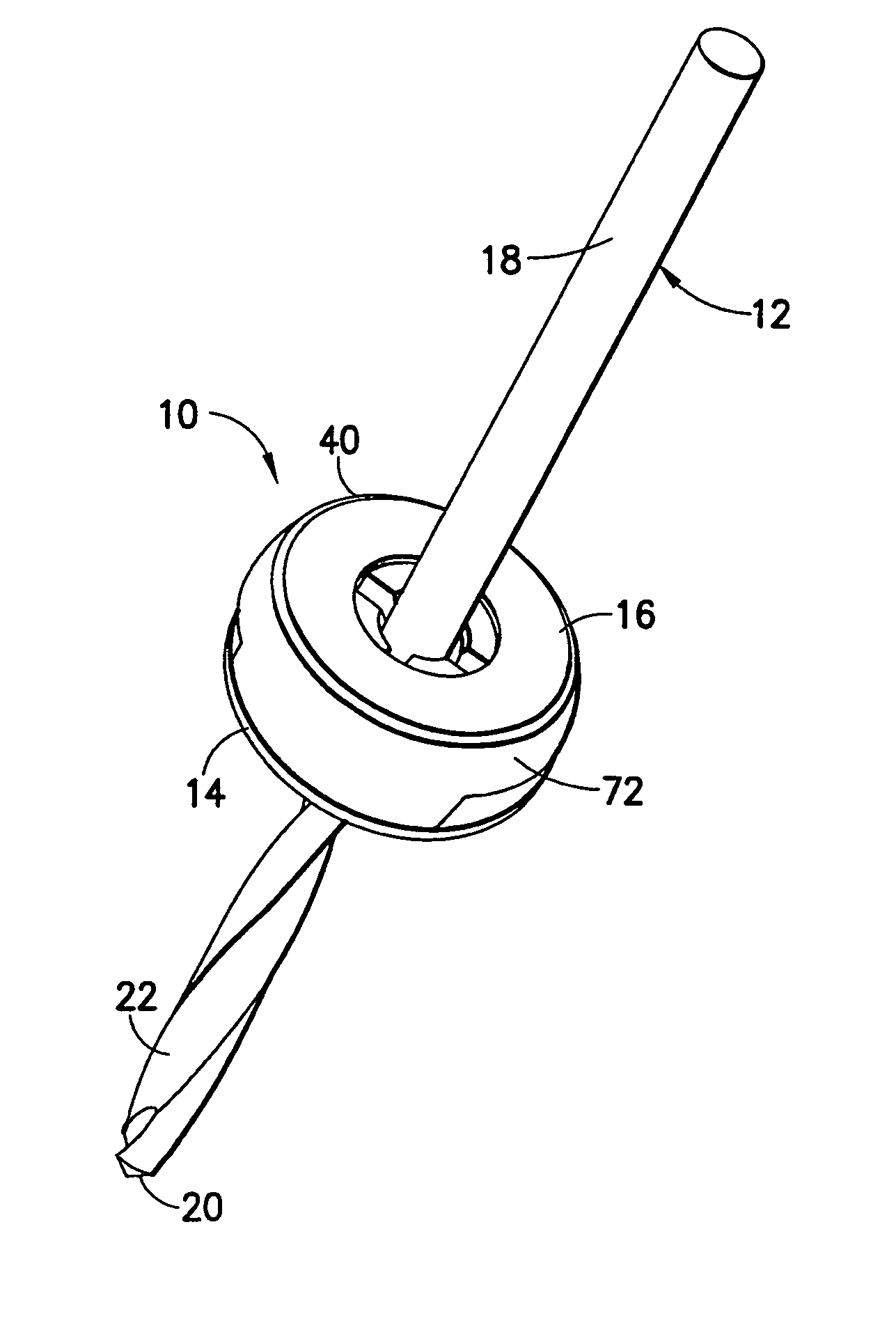
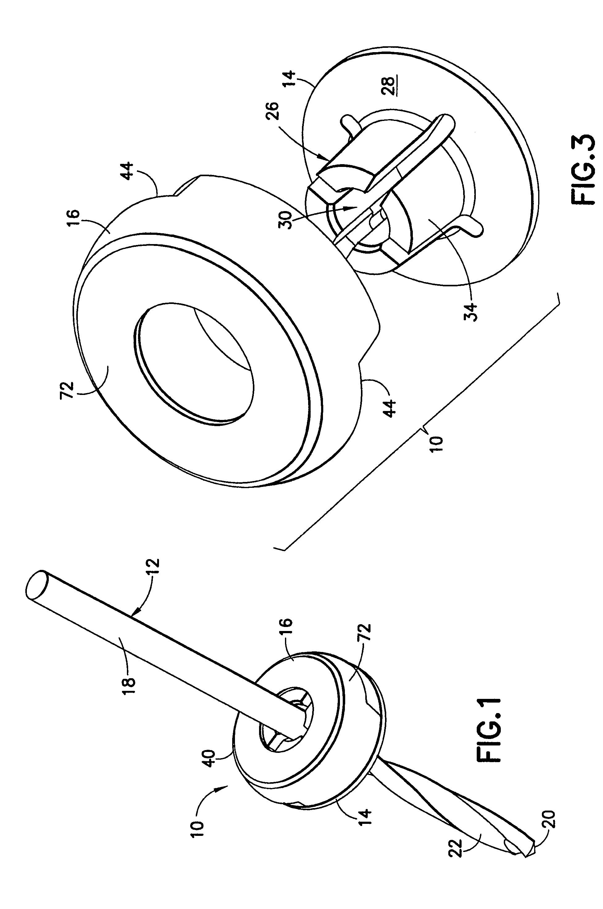
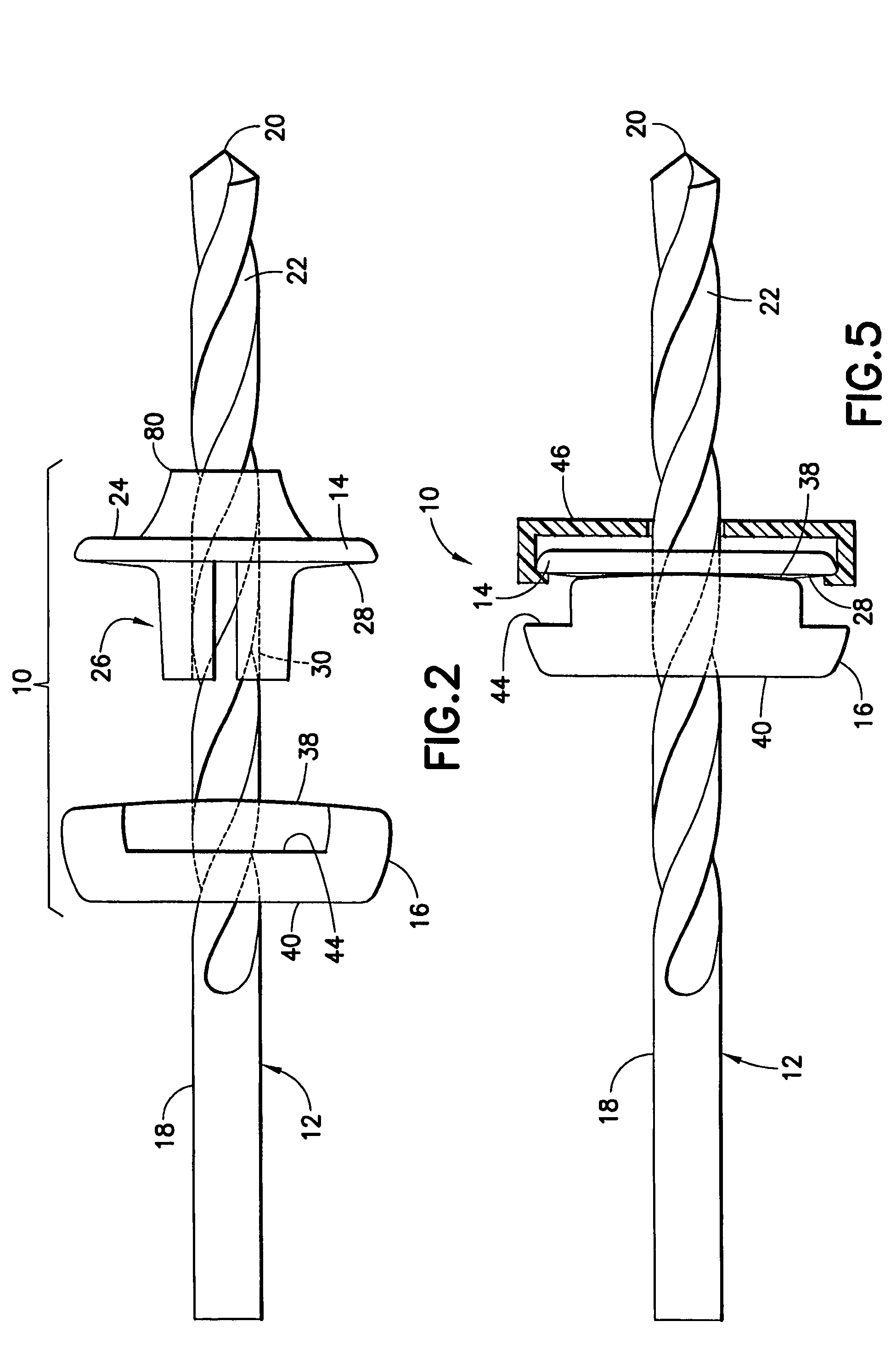
[0026]FIG. 1 shows, generally at 10, a stop for a drill bit 12 in accordance with the invention. Stop 10 includes a first member 14 and a second member 16. Drill bit 12 includes a shaft 18, a cutting point 20 and at least one groove 22.

[0027]As shown more clearly in FIGS. 2 and 3, first member 14 includes a generally planar abutment surface 24 on one side thereof and a collet 26 projecting from a rigid rear surface 28 thereof. In a preferred embodiment, rear surface 28 has a generally flat outer rim (see FIG. 3). Collet 26 includes an aperture 30 which is configured to receive shaft 18 of drill bit 12 therein. In a preferred embodiment of the invention, collet 26 includes a plurality of bendable finger elements 32 biased inwardly toward shaft 18, and collectively having an outer surface 34. More preferably at least three, and most preferably four, finger elements 32 together define a generally frusto-conical shape with the smaller end of the frustum positioned farthest from rear sur...


PUM

PropertyMeasurementUnit
diametersaaaaaaaaaa
flexibleaaaaaaaaaa
depth of penetrationaaaaaaaaaa

Abstract

A stop for a drill bit having a shaft, the stop having a first member which includes a collet. The collet is configured to receive the shaft of the drill bit and is positionable along the shaft of the drill bit. The stop also has a second member which includes a clamp, for clamping the first member in a desired position along the shaft of the drill bit by securing the collet in a desired position along the shaft of the drill bit. The stop further has an abutment surface on one of the first and second members, for limiting the depth of penetration of the drill bit into an object, the abutment surface being disposed in a fixed position along the shaft of the drill bit by the clamping of the first and second members.

Description

CROSS REFERENCE TO RELATED APPLICATIONS[0001]This application is a continuation-in-part of application Ser. No. 10 / 748,338, filed Dec. 30, 2003, now issued on May 1, 2007 as U.S. Pat. No. 7,210,881, the disclosure of which is hereby incorporated by reference.BACKGROUND OF THE INVENTION[0002]1. Field of the Invention[0003]This invention is directed to the field of hardware for use with drills, and, more particularly, to a collet collar stop for a drill bit which utilizes two molded pieces to attach to the drill bit and prevent the user from drilling too deeply into a surface by limiting the depth of penetration of the drill bit into the surface.[0004]2. Description of the Related Art[0005]Drills are common hand tools. They are used in many applications, from home repair to surgery. One common problem associated with the use of drills is that it may be difficult to identify the desired depth of a hole being drilled into a surface. In some applications, such as installing door hinges, ...

Claims


Application Information

Patent Timeline
Patent Type & Authority Patents(United States)
IPC IPC(8): B23B49/00A63F5/04A63F5/02A63F7/02G07F17/32
CPCB23B49/005Y10T408/8925A61B2019/306A61B2090/036
Inventor GREENBERG, ALEX M.MULHAUSER, PAULKIRK, III, KARL DALLAS
Owner GREENBERG SURGICAL TECH
Why Eureka
Try Eureka