Dielectric insert assembly for a communication connector to optimize crosstalk

a technology of dielectric inserts and communication connectors, applied in the direction of coupling devices, electrical apparatus, two-part coupling devices, etc., can solve the problems of performance characteristics, particularly near-end crosstalk and return loss, degrade beyond acceptable levels at these higher frequencies, and change to those systems is cost prohibitive. , the error rate of information conveyed on the signal line is greater

Active Publication Date: 2009-04-07
HUBBELL INC
View PDF31 Cites 16 Cited by
  • Summary
  • Abstract
  • Description
  • Claims
  • Application Information

AI Technical Summary

Benefits of technology

[0016]A further objective of the present invention is to provide an improved connector for controlling the crosstalk level.
[0017]A still further objective of the present invention is to provide a connector for controlling the distance between the end of the cable sheath and the sled insert of the connector.
[0018]Still another objective of the present invention is to provide a connector for maintaining the separation and twist of the wires in the cable sheath between the cable sheath and the sled insert.
[0019]Another objective of the present invention is to provide a connector with an overmold to further control crosstalk levels and to provide strain relief for the cable.

Problems solved by technology

Some performance characteristics, particularly near end crosstalk and return loss, degrade beyond acceptable levels at these higher frequencies.
However, in many cases, the wiring is pre-existing and standards define geometries and pin definitions for connectors such that making such changes to those systems is cost prohibitive.
In communications systems, reduced s / n margin results in greater error rates in the information conveyed on the signal lines.
Additionally, the rear end of the rear sled is flush with the rear end of the plug housing, so that it cannot control the distance between the cable sheath and the rear sled.

Method used


Image

  • Dielectric insert assembly for a communication connector to optimize crosstalk
  • Dielectric insert assembly for a communication connector to optimize crosstalk
  • Dielectric insert assembly for a communication connector to optimize crosstalk

Examples


second embodiment

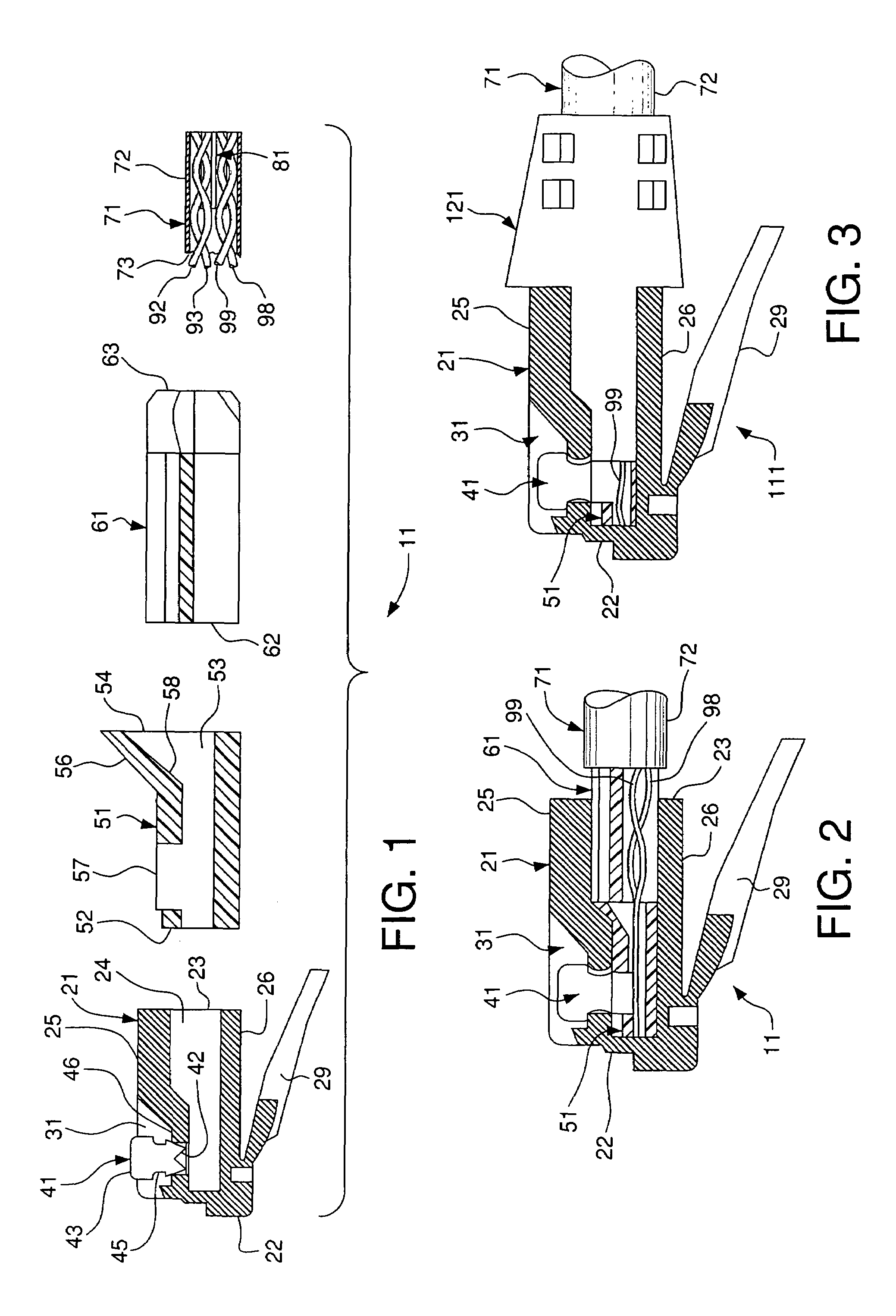
[0066]An overmold 121 may be used with the connector 111 according to the present invention, as shown in FIG. 3. The overmold 121 preferably encompasses a portion of the first insert 51, the second insert 61 and a portion of the cable 71. The overmold 121 is received within the internal chamber 24 of the plug housing 21 and terminates on the cable sheath 72 behind the cable end 73. The overmold 121 provides strain relief to the connector 111, thereby preventing the cable 71 from bending at the rear end 23 of the plug housing 21 and straining the internal components and wires. The overmold 121 also provides a secure connection between the cable sheath 72 and the plug housing 21. Preferably, the overmold 121 is a low temperature, low pressure overmold. As shown in FIGS. 19 and 20, the overmold 121 may have a projection 123 to prevent snagging the latch 29 on other cables, conduits, wires, components or other similar devices that are present in the area as the connector 111 is being pu...

third embodiment

[0067]A third exemplary embodiment of the present invention is shown in FIGS. 21-28. The connector 211 of the third embodiment is substantially similar to the connector 11 of the first exemplary embodiment with the addition of an insert assembly 201 in the connector housing 221 with the insert assembly having a higher dielectric value than the connector housing. The connector 211 substantially eliminates crosstalk in the rear portion 222 of the connector housing 221 and concentrates the crosstalk in the front portion 222 of the plug housing 221 by providing at least a portion surrounding the plurality of contacts 241 having a dielectric value of at least 4. The portion surrounding the plurality of contacts may be in the form of an insert assembly, integrally formed as one-piece with the connector housing 221, or any other suitable method such that at least a portion surrounding the plurality of contacts 241 has a dielectric value of at least 4.

[0068]The connector housing 221 has fro...

first embodiment

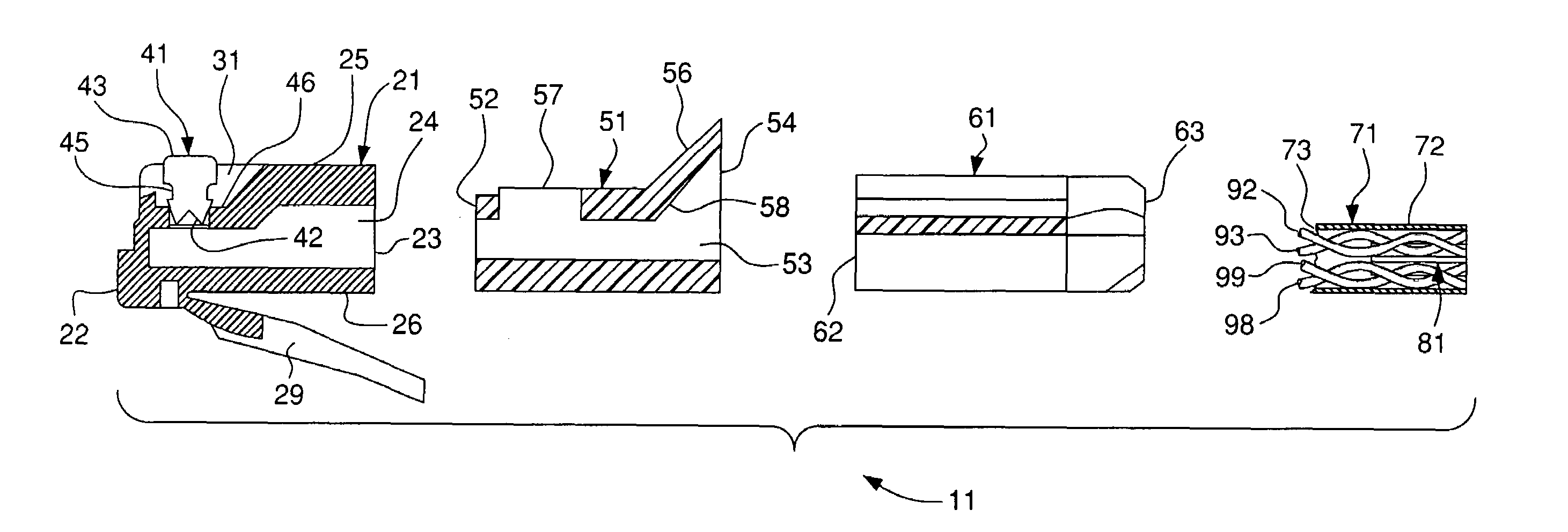
[0074]The connector 11 according to the present invention is shown unassembled in FIG. 1 and assembled in FIG. 2. The first and second inserts within the internal chamber 24 of the plug housing 21 control the length and positioning of the wires and wire pairs to effectively achieve the desired level of crosstalk in the connector.

[0075]Each of the four pairs of twisted wires emerging from the end 73 of the cable sheath 72 are maintained in their paired configuration. Preferably, two of the pairs of wires are untwisted for the length external of the cable sheath. However, these two pairs of wires may range from untwisted through varying degrees of twist external to the cable sheath depending on the desired level of crosstalk. The remaining two pairs of wires are maintained in their twisted configuration. The level of crosstalk is controlled by the degree of twist and shape of the wire pairs.

[0076]For example, in a typical Cat. 6 and 6A patch cord there are four pairs of wires within t...


PUM


Abstract

A connector for a communications system concentrates crosstalk in the front of a plug housing. The plug housing has front and rear ends. An internal chamber opens on the rear end and is defined by housing walls. A plurality of slots extend through one of the housing walls adjacent the front end and into the internal chamber. A plurality of contacts are mounted in the slots for movement between retracted positions spaced from the internal chamber and inserted positions extending into the internal chamber. An insert assembly has at least one insert member disposed adjacent at least one of the plurality of contacts. The insert assembly is made of a higher dielectric material than the plug housing.

Description

CROSS REFERENCE TO RELATED APPLICATION[0001]This application is a continuation-in-part of U.S. patent application Ser. No. 10 / 753,770, filed Jan. 9, 2004, now U.S. Pat. No. 7,223,112.FIELD OF THE INVENTION[0002]The present invention relates to a communication connector in which the crosstalk performance is concentrated in the front of the connector. More particularly, the present invention relates to a communication connector in which a portion of a connector housing is formed of a higher dielectric material. Still more particularly, the present invention relates to a communication connector in which a portion of a connector housing is formed of a higher dielectric material and is disposed adjacent contacts disposed in the housing to substantially eliminate gaps between the contacts and the higher dielectric portion of the housing. Still more particularly, the present invention relates to a communication connector in which the desired, controlled crosstalk level is achieved by minim...

Claims


Application Information

Patent Timeline
Patent Type & Authority Patents(United States)
IPC IPC(8): H01R4/50H01R24/00
CPCH01R13/6463H01R13/6473H01R13/6477H01R24/64
Inventor ABUGHAZALEH, SHADIDUPUIS, JOSEPHHABIB, NAVEDO'CONNOR, DOUG
Owner HUBBELL INC
Why Eureka
Try Eureka