Thermal receiver

a receiver and heat sink technology, applied in the field of receiver elements, can solve the problems of tearing and sticking of the elements upon separation, rendering the receiving element useless, and using such materials

Inactive Publication Date: 2009-04-07
KODAK ALARIS INC
View PDF9 Cites 12 Cited by
  • Summary
  • Abstract
  • Description
  • Claims
  • Application Information

AI Technical Summary

Problems solved by technology

A problem exists with many of the dye-donor elements and dye image-receiving elements used in thermal dye transfer systems.
At the high temperatures used for thermal dye transfer, many polymers used in these elements can soften and adhere to each other, resulting in sticking and tearing of the elements upon separation.
Areas of the dye-donor layer (other than the transferred dye) can adhere to the dye image-receiving element, rendering the receiving element useless.
However, the use of such material in high temperature extrusion coating of dye receiving layers is difficult because these materials degrade at high temperatures, resulting in unwanted reactions with other components of the dye-receiving layer.
Release agents such as those listed above can affect the quality of the image printed on the dye image-receiving layer, and can be unsuitable for use in certain receiver elements, such as those prepared by extrusion coating of the dye image-receiving layer.
Various release agents have been found to exhibit decreased effectiveness when added to an extruded dye image-receiving layer.
The release agents of the prior art can cause cross-linking and degradation of the extruded polymer mixture at the high temperatures used during extrusion, resulting in decreased image quality, such as the appearance of lines and streaks.
These compositions are not suitable for use in extruded thermal receivers.

Method used


Image

  • Thermal receiver
  • Thermal receiver
  • Thermal receiver

Examples


example 1

Thermal Receiver Elements Were Prepared Using the Following Procedures

Extruded Dye-Receiving Layer:

[0075]Dye-receiving layers having the compositions shown in Table 1 were prepared by extrusion coating as set forth below. All compounds set forth in Table 1 are in percent by weight of the dye-receiving layer.

[0076]

TABLE 1IrganoxIrganoxIrganoxIrganox 1076SamplePESPCDOSH3PO3DOPGP-70-S10763114E 201and E201C-174.5619.995.330.020.10C-273.9319.825.330.020.10.8C-373.7719.785.330.020.10.80.2C-473.7719.785.330.020.10.80.2E-173.7719.785.330.030.10.80.1E-273.8519.805.330.020.10.80.15 / 0.05

Receiver Element:

[0077]Each of the receiver elements was prepared by first extrusion laminating a paper core with a 36-38 μm thick microvoided composite polyolefin film of OPPalyte 350 K18 from ExxonMobil. A backing layer of MLT-70 composite polyolefin film from ExxonMobil was extrusion laminated to a side of the paper core opposite to the microvoided composite film to form a laminated support. An example of fo...

example 2

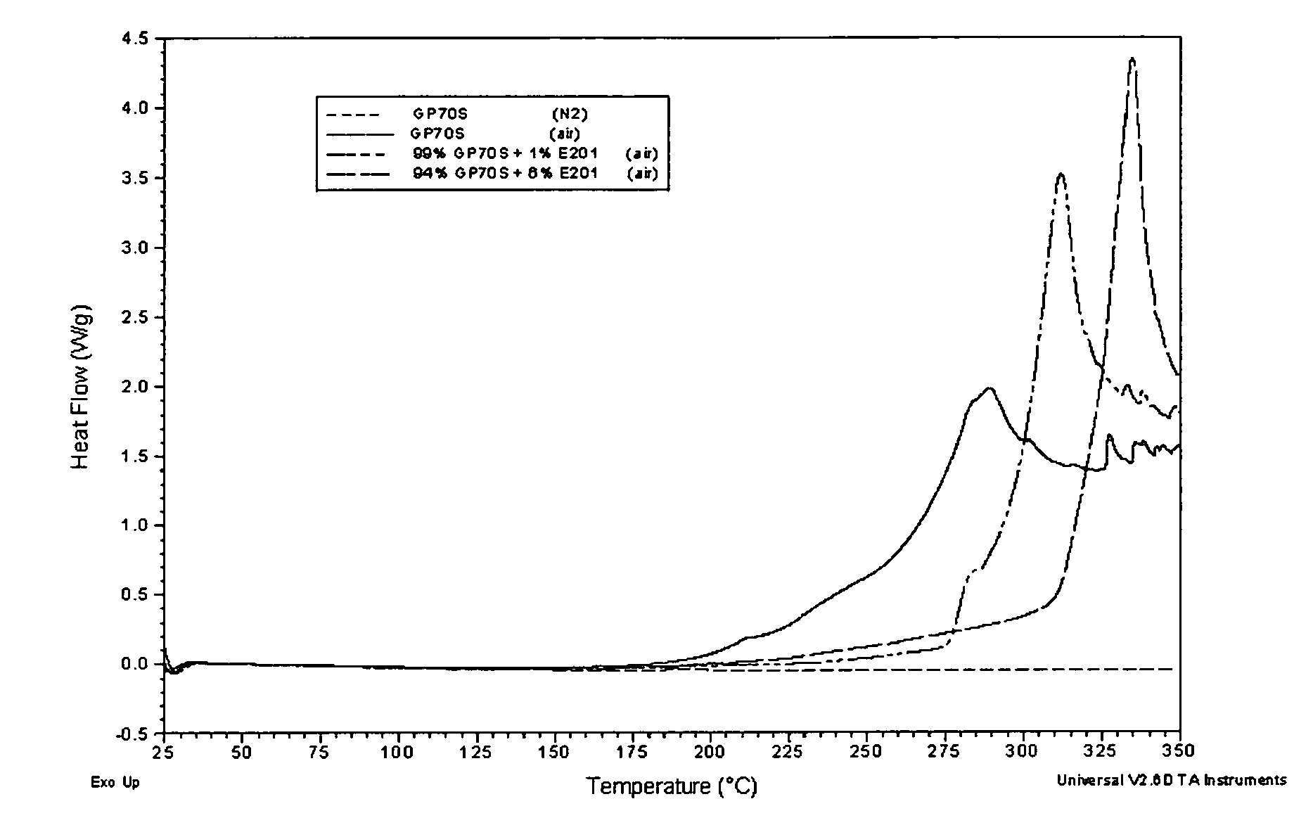
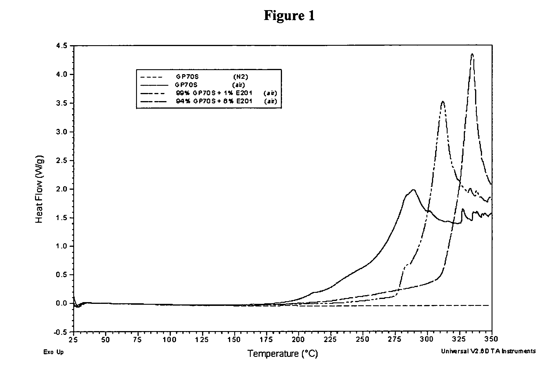
[0100]Because both GP-70-S and Ciba Irganox E 201 are liquid and mutually miscible, GP-70-S alone, Irganox E201 alone, and a mixture of the two were run in a DSC (Differential Scanning Calorimeter) at a heating rate of 10° C. / min from 25° C. to 350° C. The composition and result of each DSC scan is shown in Table 3. FIG. 1 illustrates the actual DSC scanning curves of the compositions shown in Table 3.

[0101]

TABLE 3SampleCompositionsDSC Scan ResultsC-5100 wt % GP-70-SNo exothermic decompositionobserved under nitrogen purgeC-6100 wt % GP-70-SExothermic decomposition seen after190° C. under air purge, which peakedat 287° C.E-3 99 wt % GP-70-SRapid exothermic decomposition 1 wt % Cibaoccurred after 276° C. under air purge,Irganox E 201which peaked at 312° C.E-4 94 wt % GP-70-SRapid exothermic decomposition 6 wt % Cibaoccurred after 311° C. under air purge,Irganox E 201which peaked at 335° C.

[0102]DSC scans of C-5 and C-6 in Table 3 showed that GP-70-S undergoes an oxidative decompositio...

example 3

[0103]GP-70-S alone, Irganox E201 alone, and a mixture of the two were run in a TGA (Thermal Grametric Analyzer) at a heating rate of 10° C. / min from 24° C. to 1000° C. under air atmosphere. TGA monitored the weight loss of tested samples continuously in the studied temperature range. The weight loss onset temperature was the inflection point where temperature of the tested sample started to show a significantly different rate of weight loss during a TGA scan. Usually the higher the onset temperature, the more thermally stable the sample was. The composition and result of each respective TGA scan is illustrated in Table 4.

[0104]

TABLE 4% Total% TotalWeightWeightWeight LossLossLossOnsetBetweenBetweenSampleCompositionsTemperature24-300° C.24-350° C.C-7100 wt % GP-70-S246.9° C.  9%16%E-5 99 wt % GP-70-S291.2° C.2.7%10% 1 wt % CibaIrganox E 201

[0105]Comparing the TGA scan results of C-7 and E-5, it can be seen that the presence of Irganox E201, even in a small amount, stabilizes GP-70-S ...


PUM

PropertyMeasurementUnit
temperatureaaaaaaaaaa
thicknessaaaaaaaaaa
Tgaaaaaaaaaa

Abstract

A receiver element for thermal dye transfer, a print assembly including the receiver element, and a method of printing are described wherein the receiver element includes a dye-receiving layer on a support, wherein the dye-receiving layer includes a polymer, an optional release agent, and alpha-tocopherol or a derivative thereof.

Description

FIELD OF THE INVENTION[0001]A receiver element having a dye-receiving layer containing a release agent and alpha-tocopherol, and exhibiting good coating uniformity.BACKGROUND OF THE INVENTION[0002]Thermal transfer systems have been developed to obtain prints from pictures that have been generated electronically, for example, from a color video camera or digital camera. An electronic picture can be subjected to color separation by color filters. The respective color-separated images can be converted into electrical signals. These signals can be operated on to produce cyan, magenta, and yellow electrical signals. These signals can be transmitted to a thermal printer. To obtain a print, a black, cyan, magenta, or yellow dye-donor layer, for example, can be placed face-to-face with a dye image-receiving layer of a receiver element to form a print assembly which can be inserted between a thermal printing head and a platen roller. A thermal print head can be used to apply heat from the ba...

Claims


Application Information

Patent Timeline
Patent Type & Authority Patents(United States)
IPC IPC(8): B41M5/035B41M5/50C04B41/00
CPCB41M5/52G03G7/0006G03G7/0013G03G7/002G03G7/0046B41M5/5227B41M5/5272B41M5/529B41M2205/12
Inventor KUNG, TEH-MINGPOPE, BRIAN T.KING, RONALD S.
Owner KODAK ALARIS INC
Why Eureka
Try Eureka