
Anode can for battery and manufacturing method thereof

Active Publication Date: 2009-04-07
ISHIZAKI PRESS IND
View PDF15 Cites 0 Cited by
  • Summary
  • Abstract
  • Description
  • Claims
  • Application Information

AI Technical Summary

Benefits of technology

[0008]In this manner, when the anode can and the cathode cover are connected and fixed to each other by deforming an end portion of the sidewall of the anode can so as to clamp an end of the cathode cover, strength of a junction between the anode can and the cathode cover can sufficiently be increased, because the thickness of the end portion of the sidewall (the large thickness portion) of the anode can forming the junction is relatively made larger.
[0020]In this case, by performing press working so as to move the large thickness portion toward the central axis, the anode can for a battery according to the present invention can readily be obtained from a cylindrical body having a large thickness portion projecting outwardly.

Problems solved by technology

The conventional anode can, however, has suffered from the following problems.

Method used


Image

  • Anode can for battery and manufacturing method thereof
  • Anode can for battery and manufacturing method thereof
  • Anode can for battery and manufacturing method thereof

Examples


Embodiment Construction

[0032]In the following, embodiments of the present invention will be described with reference to the figures. It is noted that the same reference characters refer to the same or corresponding components in the figures, and description thereof will not be repeated.

[0033]Referring to FIGS. 1 to 5, an anode can according to the present invention and a battery using the same will be described.

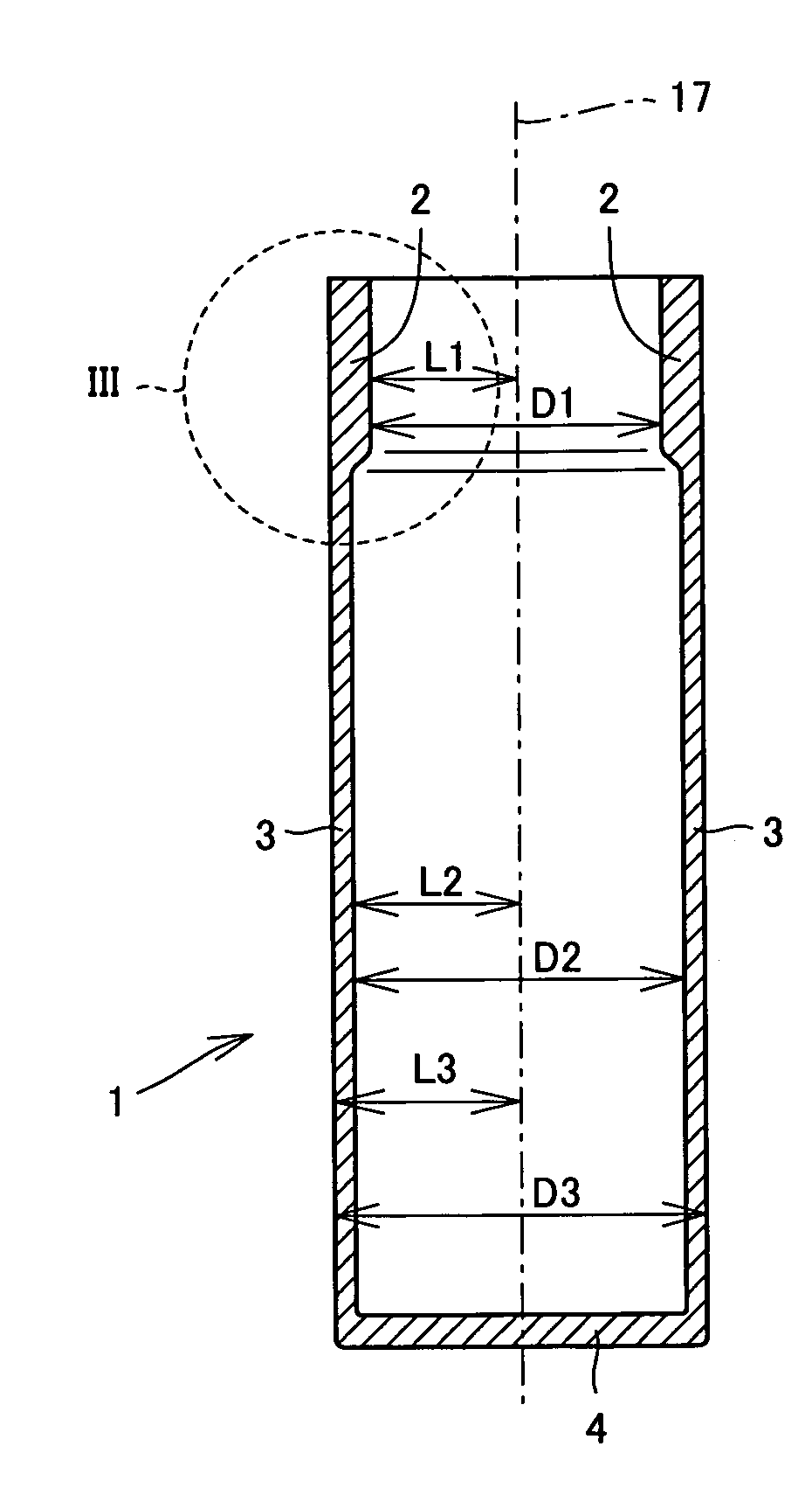
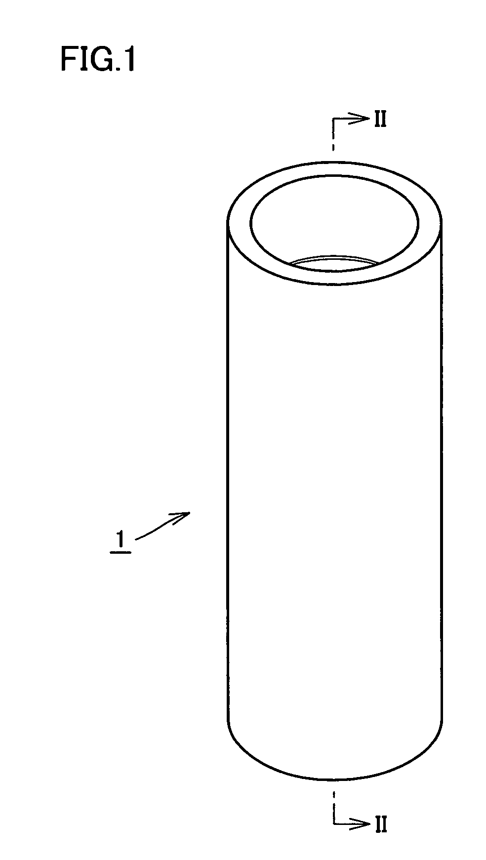
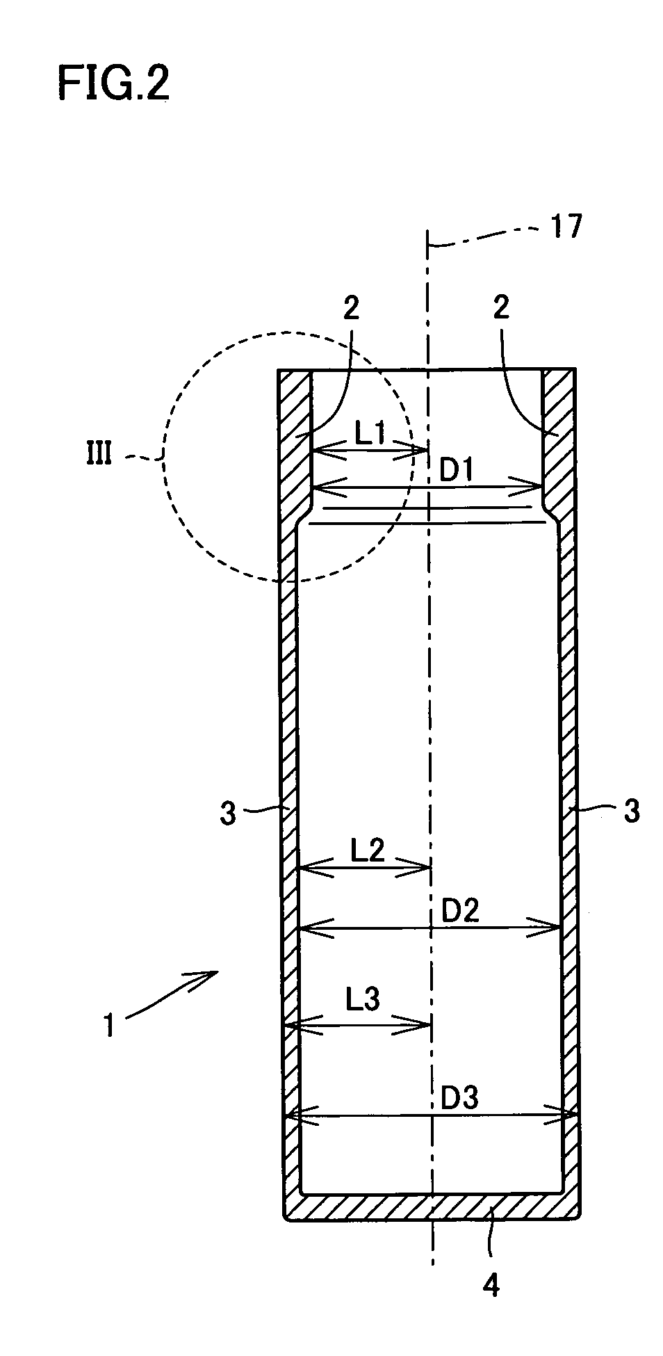
[0034]As shown in FIG. 1, an anode can 1 which is an exterior can member of a battery according to the present invention has a cylindrical shape. As can also be seen in FIG. 2, anode can 1 has an opening on the top, and has a bottom wall 4 formed in a portion facing the opening (a portion opposite to the opening). As can also be seen in FIGS. 2 and 3, in the sidewall of anode can 1, a thickness T1 of an upper end portion 2 (see FIG. 3) which is an end portion closer to the opening is larger than a thickness T2 of a sidewall small thickness portion 3 being a portion other than upper end portion 2.

[0...


PUM

PropertyMeasurementUnit
Thicknessaaaaaaaaaa
Diameteraaaaaaaaaa
Distanceaaaaaaaaaa

Abstract

A cylindrical anode can has a sidewall extending along a central axis. The sidewall has an upper end portion having a relatively large thickness and a sidewall small portion having a thickness smaller than the upper end portion. The upper end portion is located at an end of the sidewall, and the sidewall small portion is a portion other than the upper end portion. In the sidewall, a distance (L3) between an outer circumferential surface of the upper end portion and the central axis is equal to a distance (L3) between an outer circumferential surface of the sidewall small portion and the central axis. A distance (L1) between an inner circumferential surface of the upper end portion and the central axis is smaller than the distance (L2) between an inner circumferential surface of the sidewall small portion and the central axis.

Description

BACKGROUND OF THE INVENTION[0001]1. Field of the Invention[0002]The present invention relates to an anode can of a battery and a manufacturing method thereof, and more particularly to an anode can having a sufficient strength at a junction between the anode can and a cathode cover and a manufacturing method thereof.[0003]2. Description of the Background Art[0004]Conventionally, a battery in which a battery cell is accommodated in an anode can and one opening of the anode can is sealed with a cathode cover has been known (see Japanese Patent Laying-Open No. 2000-315495, for example).[0005]The conventional anode can, however, has suffered from the following problems. In order to increase a capacity of a battery while maintaining its outer dimension, a sidewall of the anode can preferably has a thickness as small as possible. On the other hand, if the thickness of the sidewall is too small, a strength of a fixing portion for fixing the cathode cover, formed by deforming an end portion ...

Claims


Application Information

Patent Timeline
IPC IPC(8): H01M2/04B21C37/30B21D17/02H01M2/02B21D22/21B21D51/36B21K21/02B21K21/12H01M50/107
CPCB21D22/21B21D51/36B21K21/12H01M2/0202B21K21/02H01M2/022Y02E60/10H01M50/107
Inventor ISHIZAKI, MORIO
Owner ISHIZAKI PRESS IND
Learn More