Organic EL drive circuit and organic EL display device using the same organic EL drive circuit

a drive circuit and drive circuit technology, applied in the direction of electric digital data processing, instruments, computing, etc., can solve the problems of large amount of drive current in the reset circuit, difficult downsizing of the organic el display panel, and high operating speed of the reset circuit, so as to reduce the power consumption of the organic el circuit

Active Publication Date: 2009-04-07
ROHM CO LTD
View PDF8 Cites 178 Cited by
  • Summary
  • Abstract
  • Description
  • Claims
  • Application Information

AI Technical Summary

Benefits of technology

[0010]An object of the present invention is to provide an organic EL drive circuit, which can reduce power consumption of an organic EL circuit by reducing power consumption of a reset circuit and can reset organic EL elements or capacitors of pixel circuits within a short time.
[0017]As a result, when the organic EL elements or the capacitors for one horizontal line are reset or one horizontal display line is undertaken by a plurality of column drivers, the resetting of a plurality of organic EL elements or capacitors of pixel circuits, which corresponds in number to terminal pins (terminal pins for R, G and B colors for a color display), undertaken by each column driver can be done simultaneously at high speed. Since only idling current flows in the amplifier circuit in the display period, it is possible to restrict power consumption of the reset circuit to thereby reduce power consumption of the organic EL circuit.

Problems solved by technology

When such drive circuit of the liquid crystal display device is applied to pixel circuits of an active matrix type organic EL display panel, down sizing of the organic EL display panel is difficult.
Therefore, a high operating speed of the reset circuit is required.
Therefore, a large amount of drive current is necessary in such reset circuit.
As a result, power consumption of the reset circuit increases with increase of the number of capacitors of the pixel circuits or of organic EL elements, which are to be reset simultaneously.

Method used


Image

  • Organic EL drive circuit and organic EL display device using the same organic EL drive circuit
  • Organic EL drive circuit and organic EL display device using the same organic EL drive circuit
  • Organic EL drive circuit and organic EL display device using the same organic EL drive circuit

Examples


Embodiment Construction

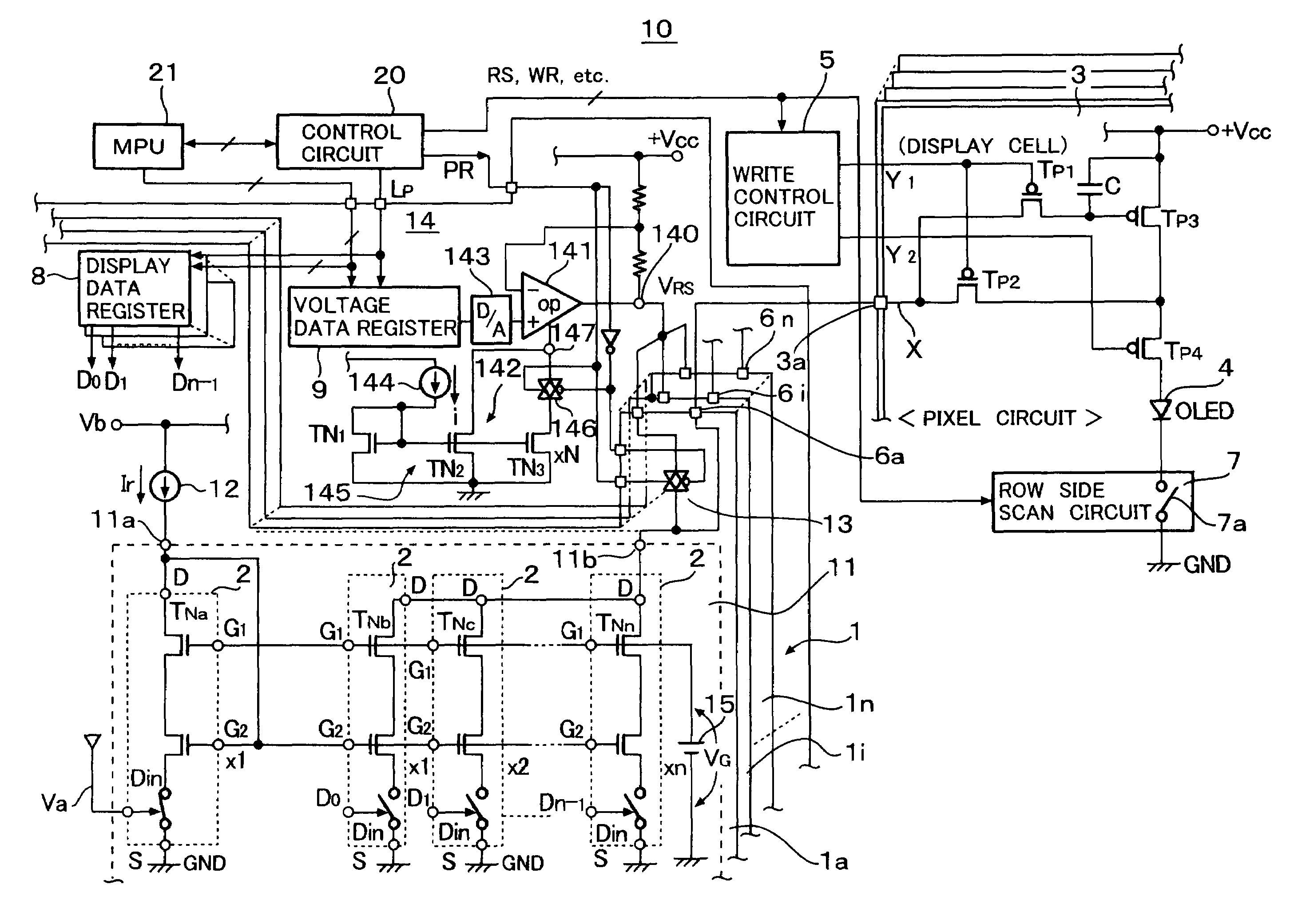
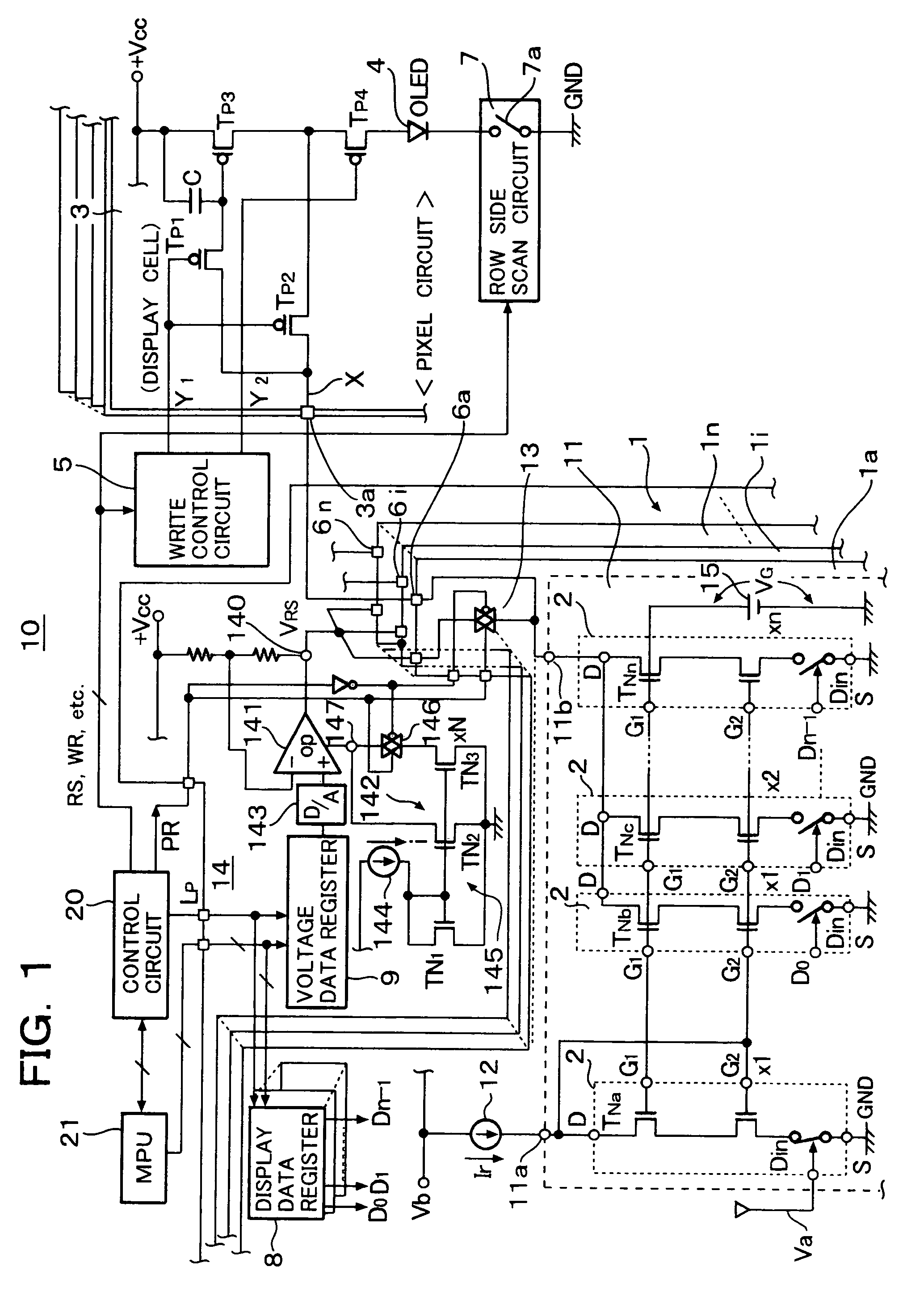
[0020]In FIG. 1, a reference numeral 10 depicts an active matrix type organic EL display panel. An organic EL drive circuit 1 takes in the form of an integrated circuit driver. The organic EL drive circuit 1 includes current drive circuits 1a to in provided correspondingly to data lines of the organic EL display panel. A reference numeral 2 indicates transistor cell circuits. The transistor cell circuits 2 constitute a D / A converter circuit 11.

[0021]A reference numeral 3 depicts pixel circuits (display cells), which are matrix-arranged in the organic EL display panel 10, a reference numeral 4 depicts organic EL elements provided in the pixel circuits 3, respectively, and a reference numeral 5 depicts a write control circuit. Reference numerals 6a to 6n depict output terminals of the current drive circuits 1a to 1n, respectively. A reference numeral 7 depicts a row side scan circuit and a numeral 7a depicts a switch circuit of the row side scan circuit 7. A reference numeral 8 depict...


PUM


Abstract

An amplifier circuit for generating a predetermined constant voltage required for resetting organic EL elements or capacitors is provided and an operating current switching circuit switches the operating current of the amplifier circuit to an idling current in a display period and to a steady operation current required to performing a reset operation in a reset period, so that a shifting time of the amplifier circuit from the idling state to the steady operation state can be shortened and a constant control voltage for resetting the organic EL elements or the capacitors can be generated in an initial portion of the reset period.

Description

BACKGROUND OF THE INVENTION[0001]1. Field of the Invention[0002]The present invention relates to an organic EL drive circuit and an organic EL display device using the same organic EL drive circuit. In particular, the present invention relates to an organic EL drive circuit capable of reducing power consumption thereof and capable of shortening a time required to reset capacitors of pixel circuits by reducing power consumption of a reset circuit for resetting constant voltages of the capacitors of the pixel circuits of an active matrix type organic EL display panel, and an organic EL display device using the same organic EL drive circuit.[0003]2. Description of the Related Art[0004]A drive circuit for driving passive matrix type organic EL elements and resetting the organic EL elements by grounding anodes and cathodes of the organic EL elements is disclosed in JPH9-232074A.[0005]On the other hand, a drive circuit of a liquid crystal display device, which drives a data line by a D / A ...

Claims


Application Information

Patent Timeline
Patent Type & Authority Patents(United States)
IPC IPC(8): G09G3/30G09G3/32
CPCG09G3/3283G09G3/325G09G2300/0861G09G2310/0248G09G2330/021G09G3/30
Inventor YAGUMA, HIROSHIKOBAYASHI, MASATO
Owner ROHM CO LTD
Why Eureka
Try Eureka