Laser scanning optical apparatus having exclusive optical elements at varying distances from receiving surfaces

a scanning optical and optical element technology, applied in the field of laser scanning optical apparatus, can solve the problems of increasing the size of the increase in the cost, and achieve the effect of downsizing the image forming apparatus

Active Publication Date: 2009-04-07
KONICA MINOLTA BUSINESS TECH INC
View PDF8 Cites 0 Cited by
  • Summary
  • Abstract
  • Description
  • Claims
  • Application Information

AI Technical Summary

Benefits of technology

[0012]An object of the present invention is to provide a laser scanning optical apparatus of a tandem type which contributes to downsizing of an image forming apparatus by not forming an unnecessary space between the laser scanning optical apparatus and image forming units.
[0013]Further, another object of the present invention is to provide a laser scanning optical apparatus which has high performance in color reproduction as well as which can attain the object above.
[0015]In the laser scanning optical apparatus according to the present invention, exclusive optical elements, each of which has at least one non-plane surface, are located in an end portion of the scanning optical system. At least one of the exclusive optical elements is at a distance from the receiving surface on which the beam transmitted by the at least one of the exclusive optical elements is scanned, and another of the exclusive optical elements is at another distance from the receiving surface on which the beam transmitted by the another of the exclusive optical elements is scanned. Therefore, the degree of freedom in arranging the exclusive optical elements is high, and it is not necessary to make the dead space between the image forming units and the laser scanning optical system, which contributes to downsizing of the image forming apparatus.
[0016]In the laser scanning optical apparatus according to the present invention, preferably, the exclusive optical elements have powers mainly in a sub-scanning direction. With this arrangement, an optical element which transmits all the beams is not required to have a large magnification in the sub-scanning direction and accordingly is not required to have a large width in the sub-scanning direction. This results in a reduction in cost and easy division into optical paths.

Problems solved by technology

Therefore, when the black image forming unit is designed to be larger than the other image forming units, a dead space D is made between the laser scanning optical apparatus 100 and the image forming units, which results in an increase in the size of the image forming apparatus.
This results in a rise in cost and becomes a bar to division into the optical paths.

Method used


Image

  • Laser scanning optical apparatus having exclusive optical elements at varying distances from receiving surfaces
  • Laser scanning optical apparatus having exclusive optical elements at varying distances from receiving surfaces
  • Laser scanning optical apparatus having exclusive optical elements at varying distances from receiving surfaces

Examples


first embodiment

See FIGS. 1 and 2

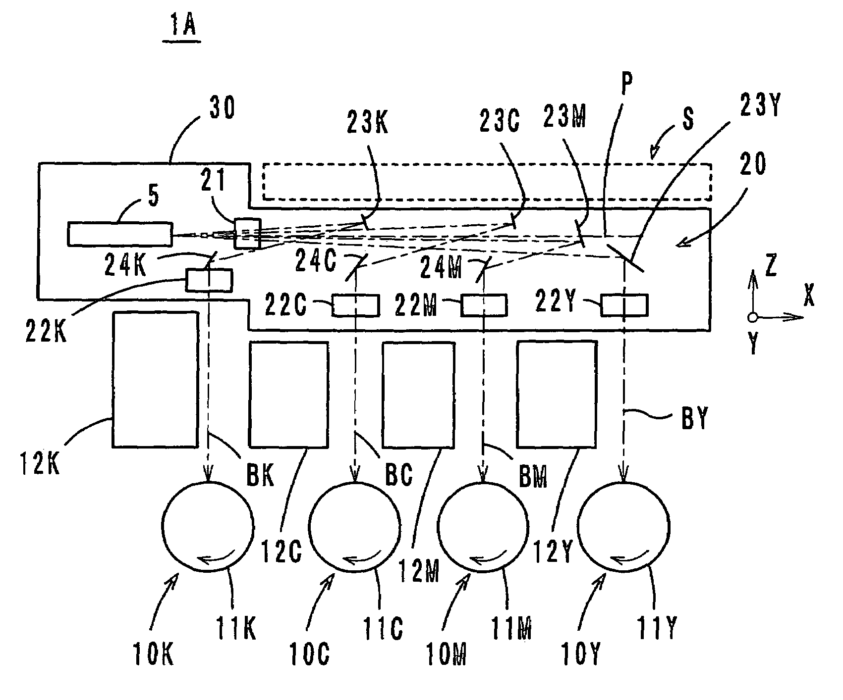
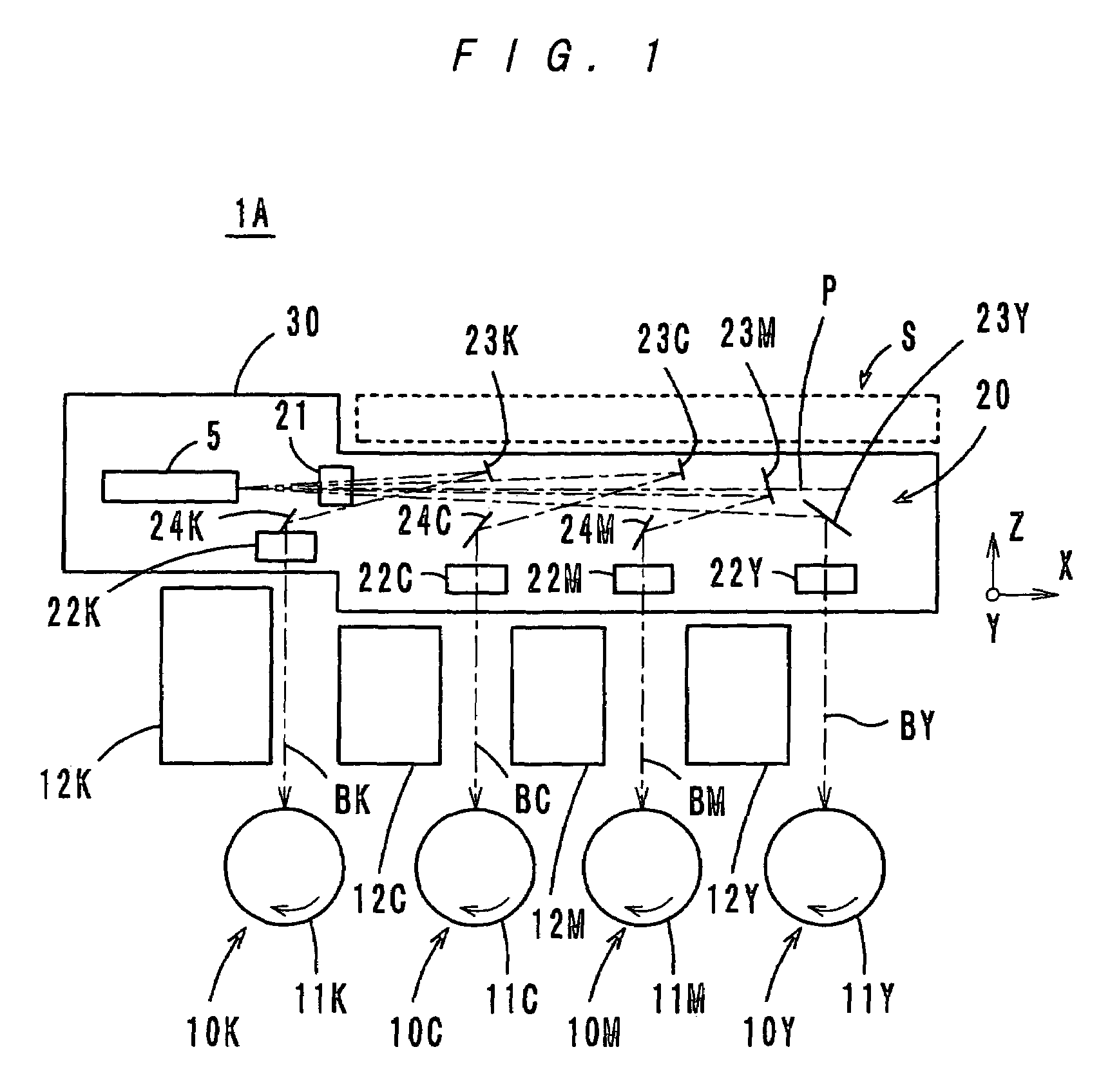
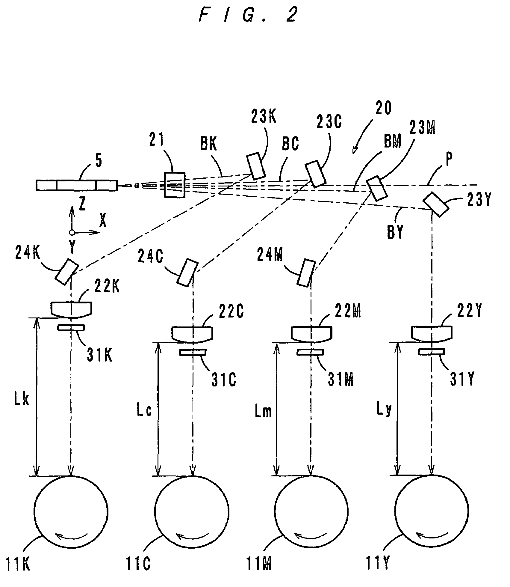
[0027]FIGS. 1 and 2 show a laser scanning optical apparatus 1A according to a first embodiment of the present invention. The laser scanning optical apparatus 1A is used for image exposure in an electrophotographic image forming apparatus of a tandem type. The apparatus 1A has four image forming units 10Y, 10M, 10C and 10K which are arranged in parallel, and laser beams BY, BM, BC and BK are scanned on photosensitive drums 11Y, 11M, 11C and 11K which are provided in the image forming units 10Y, 10M, 10C and 10K, respectively. By the laser beam scanning, images (electrostatic latent images) are formed on the photosensitive drums 11Y, 11M, 11C and 11K and are developed into a yellow, a magenta, a cyan and a black toner image. These toner images are transferred onto an intermediate transfer member (not shown) and combined (first transfer), and the thus made composite image is transferred onto a transfer paper (second transfer). This image forming process by use of an im...

second embodiment

See FIGS. 3 and 4

[0033]FIGS. 3 and 4 show a laser scanning optical apparatus 1B according to a second embodiment of the present invention. In the second embodiment, the second lenses 22Y, 22M, 22C and 22K are located such that the distance Ly between the lens 22Y and the photosensitive drum 11Y, the distance Lm between the lens 22M and the photosensitive drum 11M, the distance Lc between the lens 22C and the photosensitive drum 11C and the distance Lk between the lens 22K and the photosensitive drum 11K are mutually different, and more specifically, Ly1B are the same as those of the laser scanning optical apparatus 1A according to the first embodiment. The same parts and the same members are provided with the same reference marks, and descriptions thereof are omitted.

[0034]In the second embodiment, further, as shown in FIG. 4, the bottom of a case 35 holding the optical elements tilts at an angle in accordance with the levels of the second lenses 22Y, 22M, 22C and 22K, and a table 3...


PUM


Abstract

A laser scanning optical apparatus wherein a plural number of beams are deflected by one polygon mirror and are scanned on respective corresponding photosensitive drums via a scanning optical system. The scanning optical system has a first scanning lens which transmits all the beams, exclusive second scanning lenses which transmit exclusively the respective beams and plane mirrors for reflecting the beams. The second scanning lenses are located such that at least one of the second scanning lenses is at a distance from the corresponding photosensitive drum on which the beam transmitted by the at least one of the second scanning lenses is scanned and that another second scanning lens is at another distance from the corresponding photosensitive drum on which the beams transmitted by the another second scanning lens is scanned. For example, at least one of the exclusive optical elements is at a distance from the corresponding photosensitive drum, and the other exclusive optical elements are at another distance from the respective corresponding photosensitive drums. Alternatively, the exclusive optical elements are at mutually different distances from the respective corresponding photosensitive drums.

Description

[0001]This application is based on Japanese Patent Application No. 2005-342918 filed on Nov. 28, 2005, the content of which is incorporated herewith by reference.BACKGROUND OF THE INVENTION[0002]1. Field of the Invention[0003]The present invention relates to a laser scanning optical apparatus, and more particularly to a laser scanning optical apparatus to be employed for a color image forming apparatus such as an electrophotographic copying machine, a printer or the like.[0004]2. Description of Related Art[0005]In recent years, full-color electrophotographic image forming apparatuses, such as copying machines and printers, are generally of a tandem type, wherein four photosensitive drums for Y (yellow), M (magenta), C (cyan) and K (black) respectively are arranged in parallel, and four color images formed on the respective photosensitive drums are transferred onto an intermediate transfer member to be combined with each other.[0006]Japanese Patent Laid-Open Publications No. 2003-511...

Claims


Application Information

Patent Timeline
Patent Type & Authority Patents(United States)
IPC IPC(8): B41J15/14B41J27/00
CPCB41J2/473G02B26/123
Inventor TAKESHITA, KENJIOHATA, ATSUSHITANIGUCHI, HAJIME
Owner KONICA MINOLTA BUSINESS TECH INC
Why Eureka
Try Eureka