Adjustable height liquid cooler in liquid flow through plate

a liquid cooler and height adjustment technology, applied in the direction of lighting and heating apparatus, semiconductor/solid-state device details, laminated elements, etc., can solve the problems of increased power dissipation per area, device failure or system failure, and inability to easily dissipate hea

Active Publication Date: 2009-04-07
CURTISS WRIGHT CONTROLS
View PDF39 Cites 96 Cited by
  • Summary
  • Abstract
  • Description
  • Claims
  • Application Information

AI Technical Summary

Problems solved by technology

Electronic devices, such as electronic circuits, having high-power or densely packed components can often result in the production of heat that cannot be easily dissipated.
Excess heat will create temperatures above a normal or acceptable operating temperature range with the potential for improper operation, device failure, or system failure.
As the sizes of the components become smaller and the spacing becomes tighter, the power dissipation per area increases and the heat removal problem becomes greater.
Such monolithic liquid flow through plates, however, only provide a general cooling solution for electronic devices having moderate heat loads, such as, for example, 40-50 Watts.
Thus, they are not adapted to provide extensive cooling for high heat loads.

Method used


Image

  • Adjustable height liquid cooler in liquid flow through plate
  • Adjustable height liquid cooler in liquid flow through plate
  • Adjustable height liquid cooler in liquid flow through plate

Examples


Embodiment Construction

[0021]An example embodiment of a device that incorporates the present invention is shown in the drawings. It is to be appreciated that the shown example is not intended to be a limitation on the present invention. Specifically, the present invention can be utilized in other embodiments and even other types of devices.

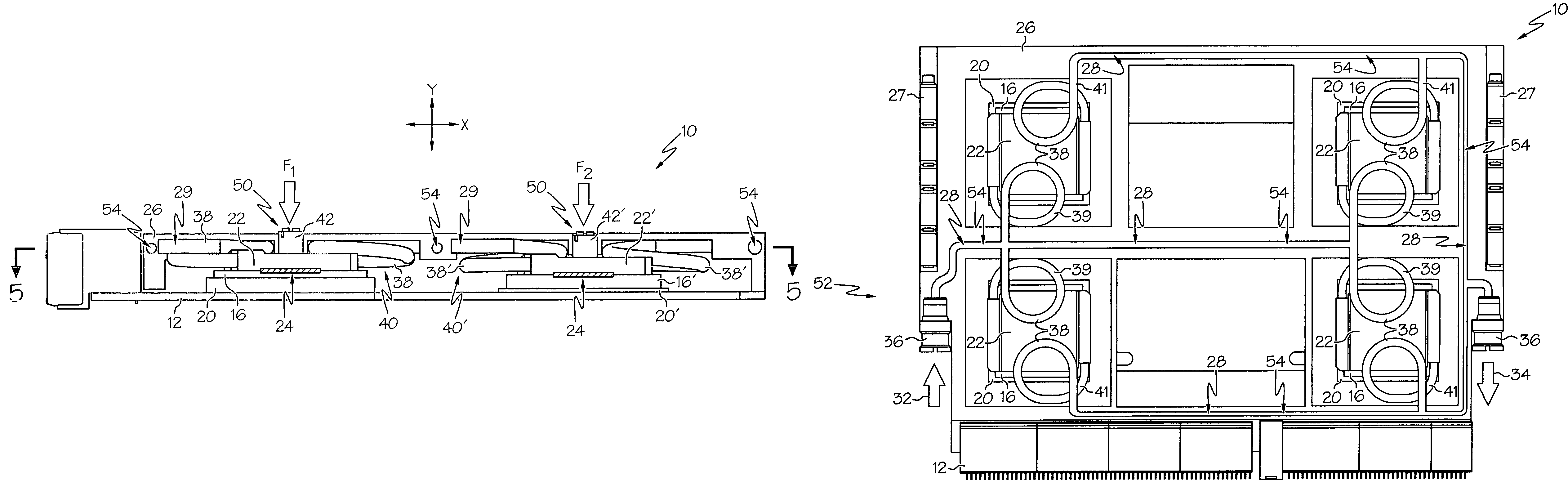
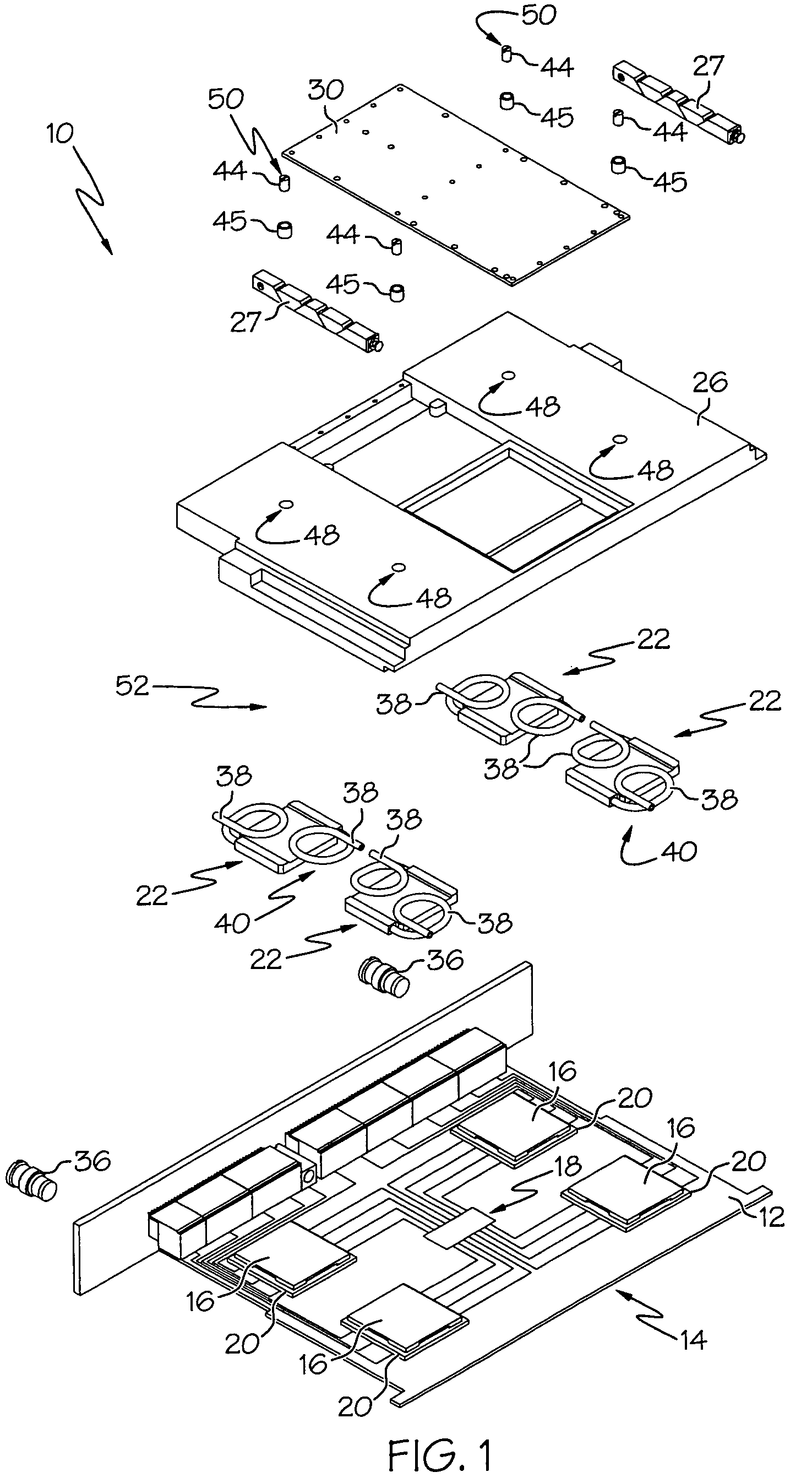
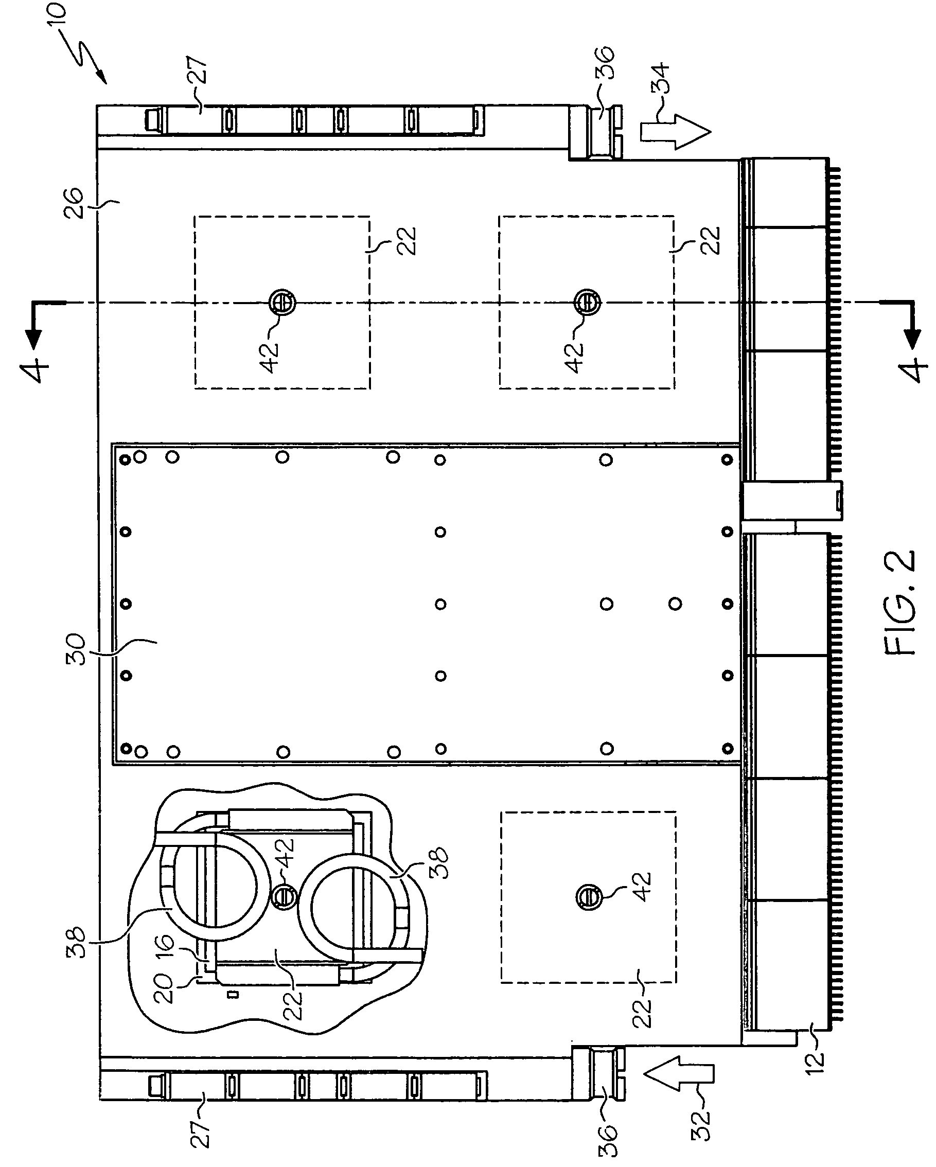
[0022]An example arrangement 10 having a cooling function in accordance with the present invention is schematically shown in FIG. 1. The arrangement 10 includes a circuit board 12 having a plurality of heat generating electronic devices 14 attached thereto. The electronic devices 14 are electrically connected to the circuit board 12. The electronic devices 14 can include either or both of high heat load devices 16 and low heat load devices 18. In the shown example, four high heat load devices 16 are shown as large integrated circuits (IC), and a variety of other supplementary electronic components are shown as low heat load devices 18. For example, as shown, the IC's 16...


PUM


Abstract

An arrangement having a cooling function is provided, comprising a circuit board, a plurality of heat generating devices attached to the circuit board, a cooling device thermally connected to one of the plurality of electronic devices, and a coolant plate. An example of the arrangement can include a source of pressurized coolant fluid connected to the coolant plate and adapted to cause the coolant fluid to be transferred between the coolant plate and the cooling device. In addition or alternatively, the arrangement can include a plurality of flexible conduits and an adjustment device adapted to selectively adjust he height of the cooling device. In addition or alternatively, a cooling apparatus within a cooling arrangement can comprise a cooling device, a coolant plate, and a coolant pathway including a first passage formed in the coolant plate and a second passage formed in the cooling device.

Description

RELATED APPLICATIONS[0001]This application claims the benefit of U.S. Provisional Application No. 60 / 720,539, filed on Sep. 26, 2005, the entire disclosure of which is hereby incorporated herein by reference.FIELD OF THE INVENTION[0002]The present invention relates generally to an apparatus for cooling electronic devices, and more particularly to an apparatus using fluid flow for cooling electronic devices.BACKGROUND OF THE INVENTION[0003]Electronic devices, such as electronic circuits, having high-power or densely packed components can often result in the production of heat that cannot be easily dissipated. Excess heat will create temperatures above a normal or acceptable operating temperature range with the potential for improper operation, device failure, or system failure. The individual components on an electronic circuit produce heat that must be conveyed away from the components and from the circuit card so that the temperatures of the components do not exceed their maximum o...

Claims


Application Information

Patent Timeline
Patent Type & Authority Patents(United States)
IPC IPC(8): H05K7/20F28D15/00
CPCH01L23/4338H01L23/473H05K7/1461H05K7/20772F28F3/12H01L2924/0002H01L2924/00
Inventor STRAZNICKY, IVANPOWER-FARDY, RICHARD JUDE
Owner CURTISS WRIGHT CONTROLS
Why Eureka
Try Eureka