Two-channel, dual-mode, fiber optic rotary joint

a fiber optic rotary joint and dual-mode technology, applied in the direction of optics, instruments, optical light guides, etc., can solve the problems of electrical power requirements, difficult fabrication of facing lens systems, and loss due to crosstalk and overlap of signal paths, so as to achieve low-profile and compact structure

Active Publication Date: 2009-04-07
PRINCETEL
View PDF5 Cites 45 Cited by
  • Summary
  • Abstract
  • Description
  • Claims
  • Application Information

AI Technical Summary

Benefits of technology

[0009]The first object of the present invention is to utilize the conventional fibers, collimators, and reflecting surfaces to realize a two-pass fiber optic rotary joints which can simultaneously transmit optical signals through a single mechanical rotational interface with a very low-profile and compact structure.
[0010]Another object of the present invention to minimize the need for maintaining precise axial alignment between the rotating and non-rotating elements of a two channel fiber optic rotary joint so that it could be used in any harsh environments such as temperature change, vibration and shock.

Problems solved by technology

The disadvantage of active FORJ is requirement for electrical power.
However, the transmission results in difficulties when it is desired to transmit two channels separately from each other through a single rotation interface.
The drawback of this design is that the losses due to crosstalk and overlap of the signal paths would be pretty significant.
But the facing lens systems are very difficult to be fabricated.
But it could be very difficult for the magnetic interaction to accurately ensure the synchronous rotation of the rotor and the rotating member.

Method used


Image

  • Two-channel, dual-mode, fiber optic rotary joint
  • Two-channel, dual-mode, fiber optic rotary joint
  • Two-channel, dual-mode, fiber optic rotary joint

Examples


Embodiment Construction

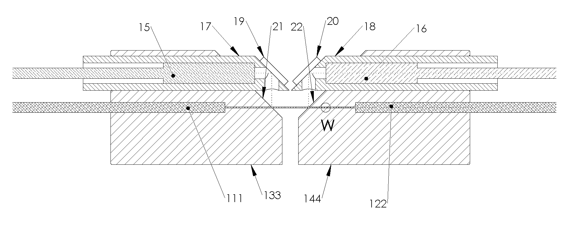
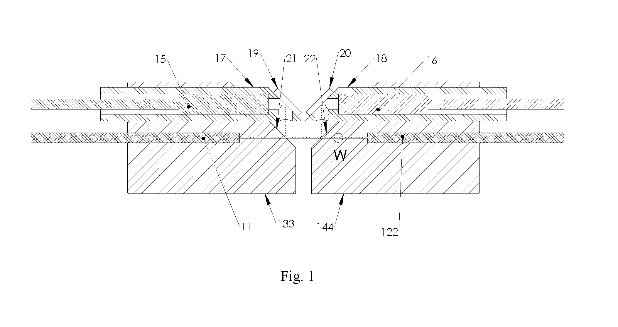
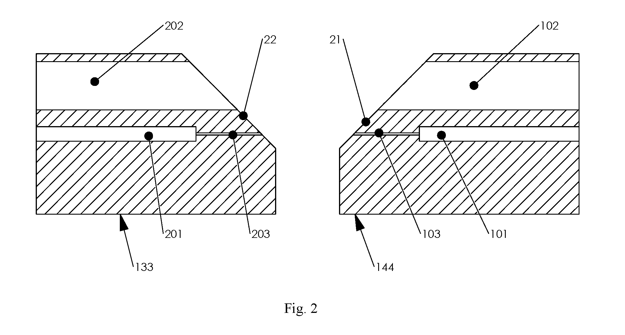
[0014]FIG. 1 illustrates a basic design of a two-channel fiber optical rotational interface. The holder 133 and 144 can be rotatable relative to each other. The axis of the rotation is the geometrical axis 101, 201 of the holder 133 and 144 (shown in FIG. 2). The first channel of light pass consists of a optic fiber 111 which is fixed on the axis 101 of holder 133, and another optic fiber 122 which is fixed on the axis 201 of holder 144. The diameter of the optic fiber is about 0.125 mm. The holder 133 and 144 have a through central hole 103, 203 at the diameter of 0.126 mm, slightly larger than the diameter of fiber 111 and 122. Fiber 111 should be longer than fiber 122 so that it could get into the central hole 103 of holder 144. The end surfaces of fiber 111 and 122 are oppositely positioned inside the central hole 103 of holder 144 on the rotational axis but separated by a clearance about 0.5 um. An enlarged view inside of central hole of holder 144 is shown in FIG. 3. When the ...


PUM


Abstract

A two-channel fiber optic rotary joint of this invention can transmit simultaneously optic signals along two optic passes through a single mechanical rotational interface. The first channel of light path consists of a pair of fibers, co-axially fixed in 2 holders respectively. The light signal from one of the fiber can be directly coupled into another fiber. The second channel of light path is off-axis arranged, including a pair of conventional collimators, a pair of first reflecting surfaces and a pair of second reflecting surfaces. The light signal emitted from one of the said conventional collimator will be reflected by one of the said first reflecting surface, one of the said second reflecting surface, another said second reflecting surface, and another said first reflecting surface, then coupled into another said conventional collimator.

Description

BACKGROUND OF THE INVENTION[0001]1. Field of the Invention[0002]The invention is related to two channel fiber optic rotary joint in the field of optic transmission through a mechanical rotational interface.[0003]2. Description of Related Art[0004]The Fiber optic Rotary Joint (FORJ) is the opto-mechanical device which allows uninterrupted transmission of an optical signal in a fiber guide through a rotational interface to a stationary apparatus. FORJ can be categorized as active and passive. An active FORJ consists of a light on either rotor side or stator side and a photo detector on another side and the signal transmission is limited to unidirectional. The disadvantage of active FORJ is requirement for electrical power. The passive FORJ is intended to transfer optical signals from fiber to fiber without any electronic or electrical units. The use of FORJ can be widely found in missile guidance systems, robotic systems, remotely operated vehicles (ROVs), oil drilling systems, sensin...

Claims


Application Information

Patent Timeline
Patent Type & Authority Patents(United States)
IPC IPC(8): G02B6/26G02B6/32
CPCG02B6/3604
Inventor ZHANG, BOYING B.ZHANG, HONG
Owner PRINCETEL
Why Eureka
Try Eureka