
Seat belt retractor and seat belt apparatus

Inactive Publication Date: 2009-04-14
JOYSON SAFETY SYST JAPAN KK
View PDF32 Cites 26 Cited by
  • Summary
  • Abstract
  • Description
  • Claims
  • Application Information

AI Technical Summary

Benefits of technology

[0013]According to the first embodiment of the present invention relating to the seat belt storing control by the seat belt retractor, the electric motor can be used to conduct the seat belt winding action so as to reduce the risk of making the vehicle occupant uncomfortable as well as to prevent the seat belt from being kept in the unwound state. Therefore, this embodiment may provide a seat belt retractor capable of providing detailed control with regard to the seat belt winding action using the electric motor.
[0016]According to the second embodiment relating to the seat belt storing control by the seat belt apparatus, the electric motor can be used to conduct the seat belt winding action so as to reduce the risk of making the vehicle occupant uncomfortable as well as to prevent the seat belt from being kept in the unwound state. Therefore, a seat belt apparatus capable of providing detailed control with regard to a seat belt winding action using the electric motor is provided.
[0019]As described in the above, the present disclosure may relate to the structure of a seat belt retractor for winding a seat belt for occupant restraint according to the driving of an electric motor. The present disclosure may provide a control mode in which an electric motor is controlled to rotate in the belt winding direction on the condition that the wearing of the seat belt on a vehicle occupant is cancelled and a vehicle door corresponding to the seat belt is changed from a closed state to an open state, thereby reducing the risk of making the vehicle occupant uncomfortable due to the seat belt winding action as well as preventing the seat belt from being kept in the unwound state.

Problems solved by technology

It should be noted that if a seat belt is kept in a state withdrawn from a spool in a seat belt retractor of this kind, there is a risk that trouble will occur in which the seat belt itself or a tongue attached to the seat belt is caught by the vehicle door.
However, this structure makes the vehicle occupant uncomfortable when the vehicle occupant cancels the wearing of the seat belt but changes his or her mind and decides to wear the seat belt again.

Method used


Image

  • Seat belt retractor and seat belt apparatus
  • Seat belt retractor and seat belt apparatus
  • Seat belt retractor and seat belt apparatus

Examples


Embodiment Construction

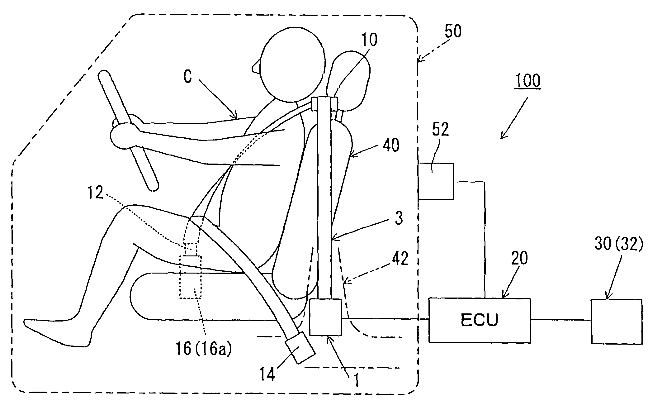
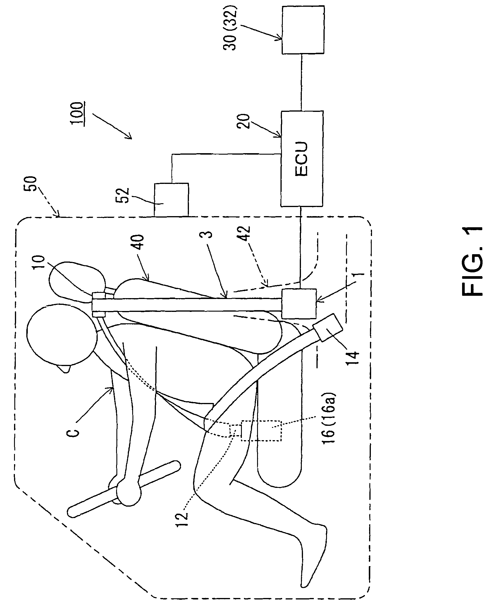
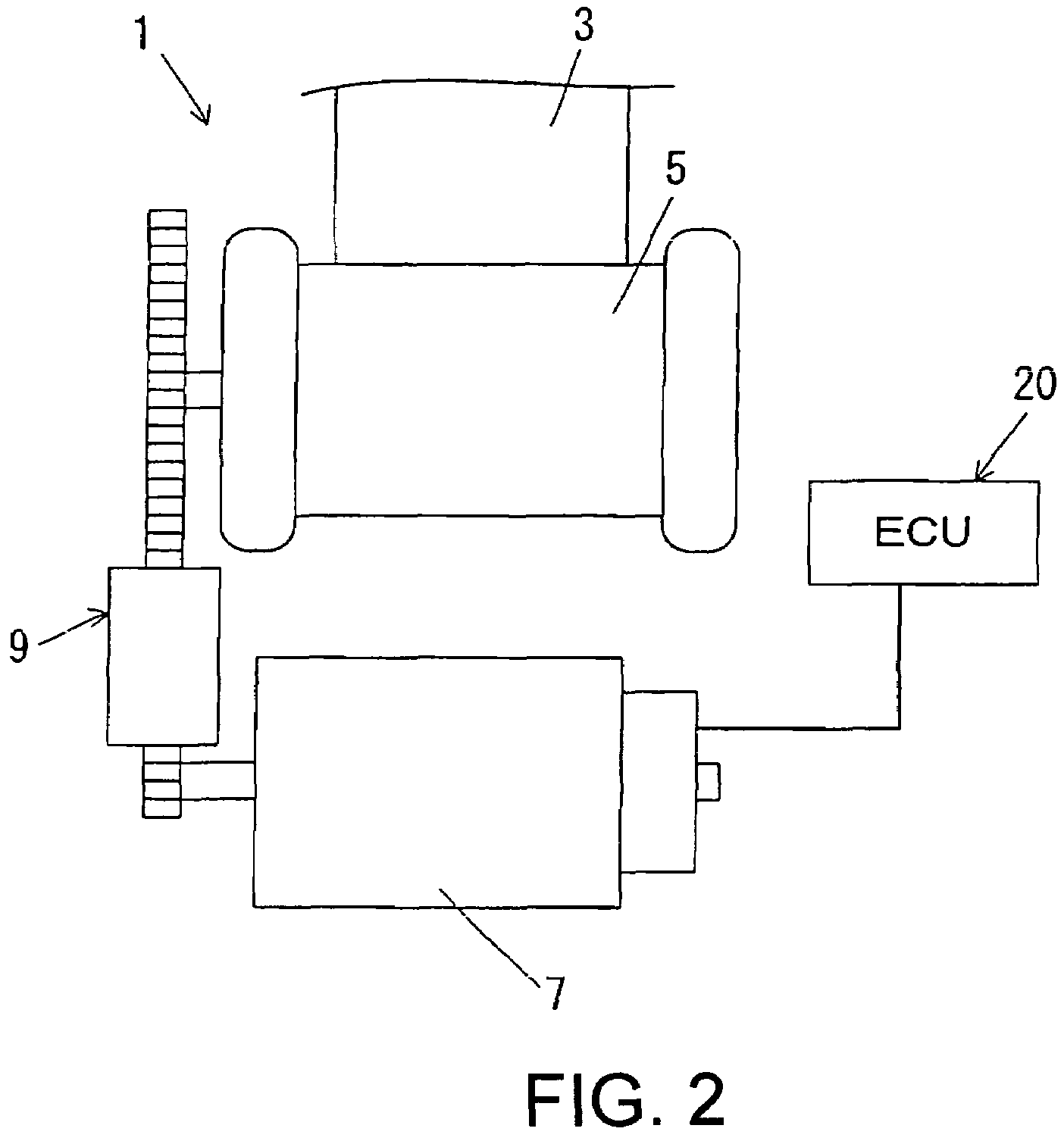
[0025]Hereinafter, various embodiments of the present invention will be described in detail with reference to the drawings. First, description will be made in regard to embodiments of the present invention with reference to FIG. 1 and FIG. 2.

[0026]FIG. 1 shows a schematic structure a seat belt apparatus 100 according to an embodiment of the present invention. FIG. 2 shows a schematic structure of a seat belt retractor 1.

[0027]As shown in FIG. 1, the seat belt apparatus 100 is a seat belt apparatus for a vehicle to be installed in an automotive vehicle. The seat belt apparatus 100 can mainly comprise a seat belt retractor 1, a seat belt 3, a deflection fitting 10, a tongue 12, an outer anchor 14, a seat belt buckle 16, and an ECU 20. In addition, an input element 30 can be installed in the vehicle to detect various kinds of information and to input such detected information into the ECU 20. Such information can include information about a collision prediction or a collision occurrenc...


PUM


Abstract

The disclosed seat belt retractor and seat belt apparatus may be used to provide a technology effective for reducing the risk of making a vehicle occupant uncomfortable with regard to the seat belt winding action. A seat belt retractor and seat belt apparatus may comprise an electric motor, a spool capable of winding and unwinding a seat belt for occupant restraint, and a controller configured to perform a control mode in which the electric motor is controlled to rotate in a belt winding direction based on the status of a wearing of the seat belt on a vehicle occupant and the status of a vehicle door corresponding to the seat belt.

Description

BACKGROUND[0001]The present invention relates to a seat belt retractor to be installed in a vehicle.[0002]Conventionally, a seat belt apparatus is known, which is structured to protect an occupant in a vehicle by a seat belt (or webbing) restraining the occupant. For example, Japanese PCT International Application Publication 2003-507252 (the '252 Publication) discloses a structure of a seat belt retractor of a seat belt apparatus in which a spool (or a winding shaft) can be rotated for the winding and unwinding of a seat belt by an electric motor.[0003]The technology described in the '252 Publication proposes a possibility of using an electric motor to conduct the seat belt winding action of the spool in the structure of the seat belt retractor. When this structure is used for the control (or the seat belt storing control) of the winding up of a seat belt in order to prevent the seat belt from being kept in the unwound state, the control is required to prevent making the vehicle oc...

Claims


Application Information

Patent Timeline
IPC IPC(8): B60R22/34B65H75/48
CPCB60R22/02B60R22/03
Inventor TANAKA, KOJI
Owner JOYSON SAFETY SYST JAPAN KK
Learn More