Monitoring device for a medium voltage overhead line

a monitoring device and overhead line technology, applied in the direction of line-transmission details, digital computer details, instruments, etc., can solve the problems of increased competition between electricity providers, network losses, interruption of electricity supply, etc., to reduce computational overhead, simplify the construction of individual measurement sensors, and enhance system efficiency

Inactive Publication Date: 2009-04-14
FMC TECH LTD
View PDF14 Cites 241 Cited by
  • Summary
  • Abstract
  • Description
  • Claims
  • Application Information

AI Technical Summary

Benefits of technology

[0003]It has been found that even in highly developed countries, approximately 10% of all electricity generated is lost within the electricity networks themselves. This figure rises to almost 25% in less developed nations. One of the main reasons for this loss of power is the electricity provider's lack of knowledge of the electricity flowing in their medium voltage networks. Faults can go undetected for long periods of time and once detected are often difficult to locate over an expansive medium voltage network. By increasing their knowledge of the electrical properties in their medium voltage networks by closely monitoring their networks, electricity providers can significantly reduce the amount of electricity lost in their medium voltage networks and make considerable savings in the cost of generating the electricity. Furthermore, by closely monitoring their networks electricity providers will be in a better position to correct faults in their networks quickly with a minimum of inconvenience to their customers, thereby providing an improved quality of supply to their customers.
[0062]In one embodiment of the invention, there is provided a system in which any three adjacent measurement sensors may be combined to form arbitrary triplets to form a variety of detectors. This will increase the number of measurements that can be carried out on the overhead line and should one of the measurement sensors fall, the other two measurement sensors may form part of a different measurement device.

Problems solved by technology

Recently, deregulation of the electricity supply market has led to increased competition between electricity providers.
This has led to competition between the different providers over a whole range of different issues including pricing and quality of supply.
Furthermore, due to deregulation, network losses and interruption to electricity supply are now being penalised.
It has been found that even in highly developed countries, approximately 10% of all electricity generated is lost within the electricity networks themselves.
One of the main reasons for this loss of power is the electricity provider's lack of knowledge of the electricity flowing in their medium voltage networks.
Faults can go undetected for long periods of time and once detected are often difficult to locate over an expansive medium voltage network.
Although simple to install, these devices are not entirely suitable due to the fact that it is extremely difficult to obtain an accurate reading of the electrical properties in the line when monitoring those properties from a distance.
This geometry information is difficult to obtain, time consuming, costly, and once the geometry is set, is subject to changes from environmental conditions, i.e. temperature of the line, sag, wind movement and subsidence of the poles whereon the device is mounted.
These devices are therefore relatively inaccurate devices that cannot provide the required accuracy for monitoring a line and hence the medium voltage network sufficiently.
There are, however, problems associated with known types of line mounted monitoring devices.
By having a single device the calculations on the line that may be carried out are limited.
Impending earth faults are not detected and real time line loading information as well as reactive current information cannot be obtained from the single sensor.
Furthermore, the ability to recognise reactive earth faults down to in the region of 1 Amp is not possible.
Therefore, the required level of information cannot be obtained by using the known types of monitoring devices.

Method used


Image

  • Monitoring device for a medium voltage overhead line
  • Monitoring device for a medium voltage overhead line
  • Monitoring device for a medium voltage overhead line

Examples


Embodiment Construction

[0064]The invention will now be more clearly understood from the following description of some embodiments thereof given by way of example only with reference to the accompanying drawings in which:

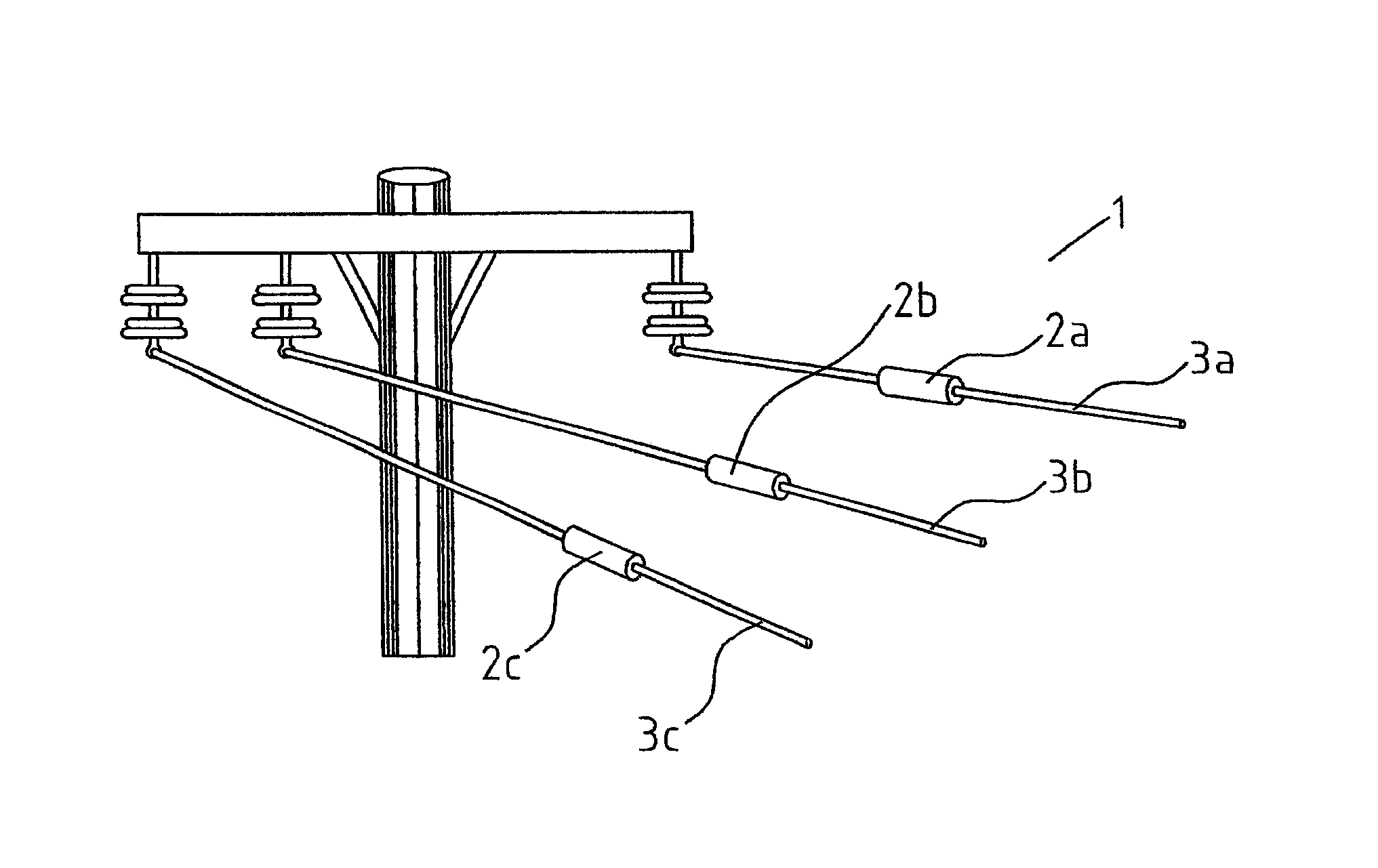
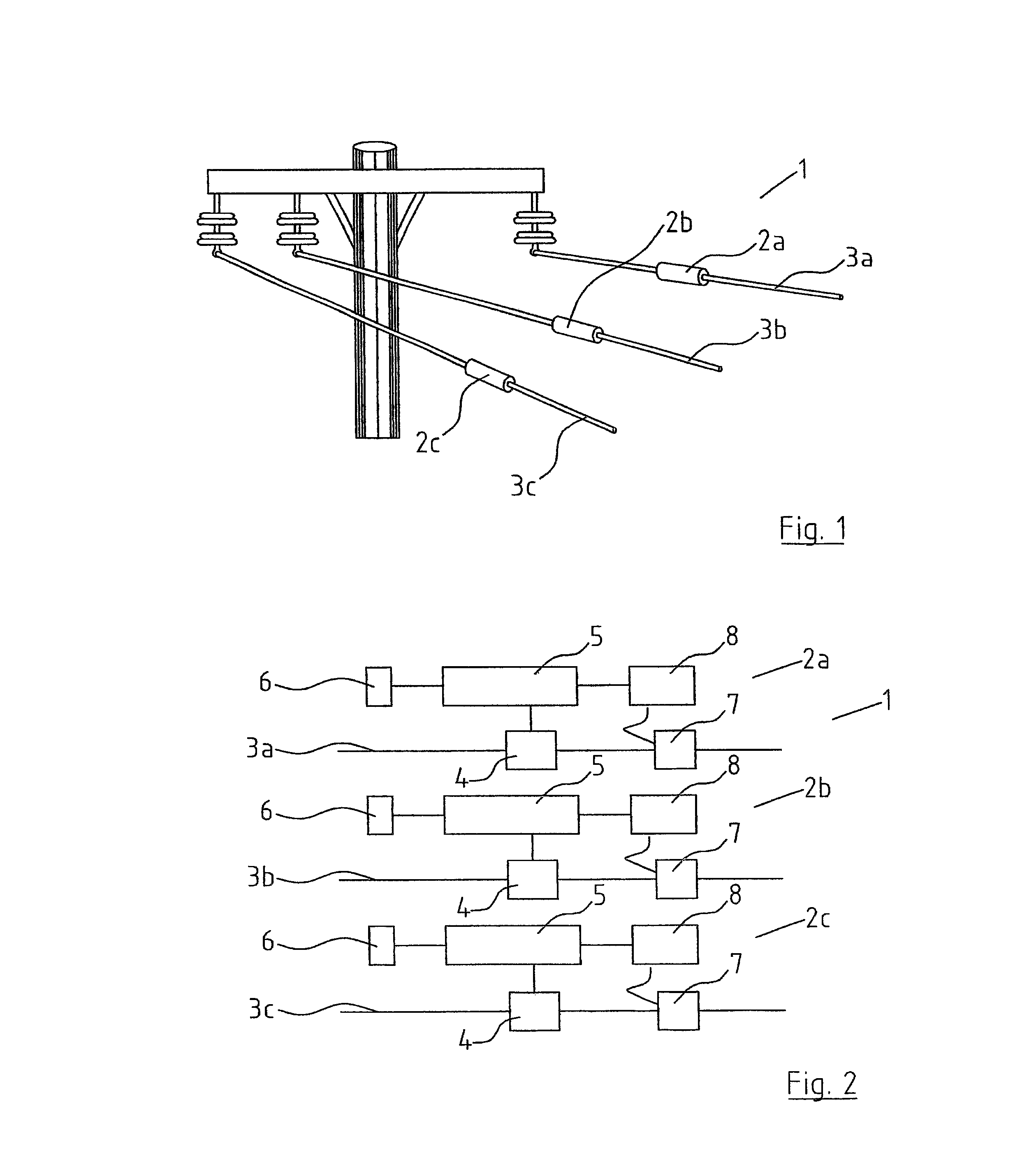
[0065]FIG. 1 is a perspective view of a monitoring device according to me invention;

[0066]FIG. 2 is a block diagram of a monitoring device according to the invention;

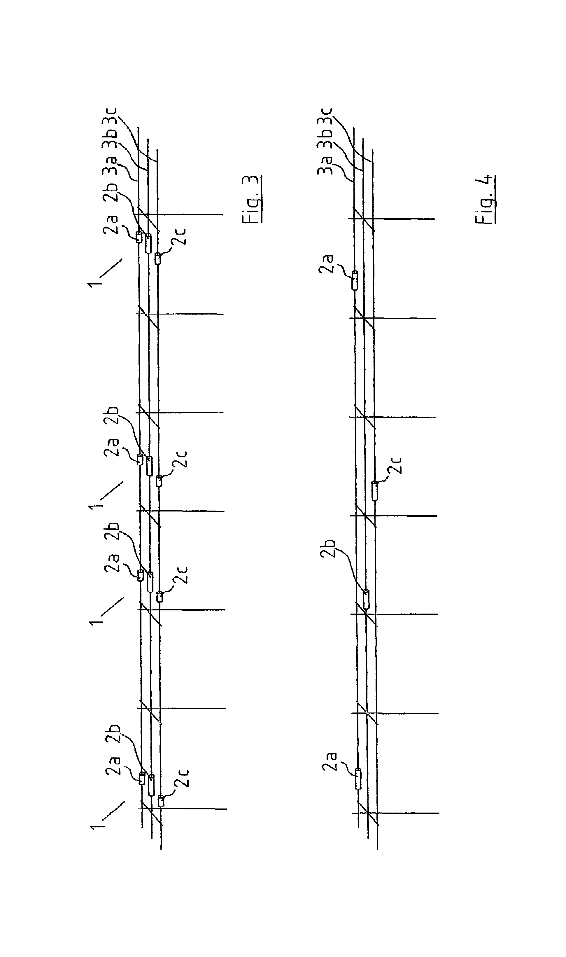
[0067]FIG. 3 is a perspective view of a length of medium voltage overhead line having a number of monitoring devices distributed thereon;

[0068]FIG. 4 is a perspective view of a length of medium voltage overhead line showing an alternative distribution of monitoring devices along the line;

[0069]FIG. 5 is a perspective partially cut-away view of a measurement sensor according to the invention;

[0070]FIG. 6 is a diagrammatic view of a system according to the invention;

[0071]FIG. 7 is a typical view of a user interface of the control centre computer;

[0072]FIG. 8 is a view of a user interface of the control centre computer with auto...


PUM


Abstract

A monitoring device (1) for monitoring the electrical properties of a medium voltage overhead line (3) in a medium voltage network comprises three separate measurement sensors (2a, 2b, 2c), each being adapted for direct connection onto a medium voltage overhead line. Each of the measurement sensors has means to draw operating power from the medium voltage overhead line. The measurement sensors measured results may be combined for accurate measurement analysis.

Description

[0001]This invention relates to a monitoring device for monitoring the electrical properties of a medium voltage overhead line in a medium voltage network, the monitoring device comprising means to measure the electrical properties of the medium voltage line and means to communicate the measured electrical properties to a control centre computer of the medium voltage network.[0002]Recently, deregulation of the electricity supply market has led to increased competition between electricity providers. It is now quite common for companies and households to have a choice of several different electricity providers when deciding on an electricity provider to supply their electricity needs. This has led to competition between the different providers over a whole range of different issues including pricing and quality of supply. Electricity providers are now having to supply their customers with less expensive electricity while still guaranteeing the same or improved quality of supply to the...

Claims


Application Information

Patent Timeline
Patent Type & Authority Patents(United States)
IPC IPC(8): H04Q9/00G01R15/14
CPCG01R15/142
Inventor O'SULLIVAN, CHARLES BRENDANQUINLAN, MICHAEL MARTIN
Owner FMC TECH LTD
Why Eureka
Try Eureka