Stereoscopic image display device using image splitter, adjustment method thereof, and stereoscopic image display system
- Summary
- Abstract
- Description
- Claims
- Application Information
AI Technical Summary
Benefits of technology
Problems solved by technology
Method used
Image

Examples
fifth embodiment
[0189]FIGS. 17 and 18 show an image splitter of the invention.
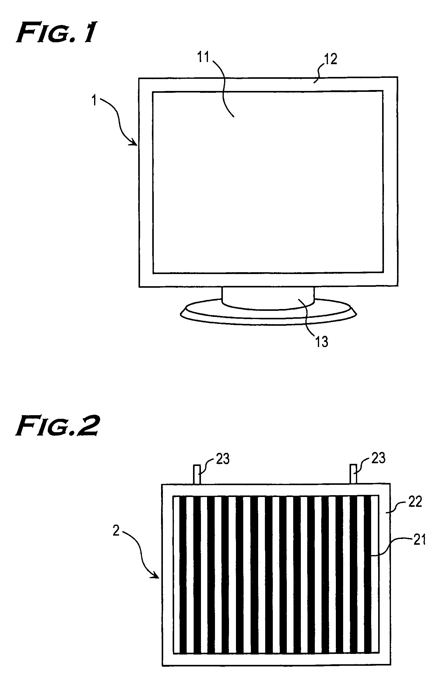
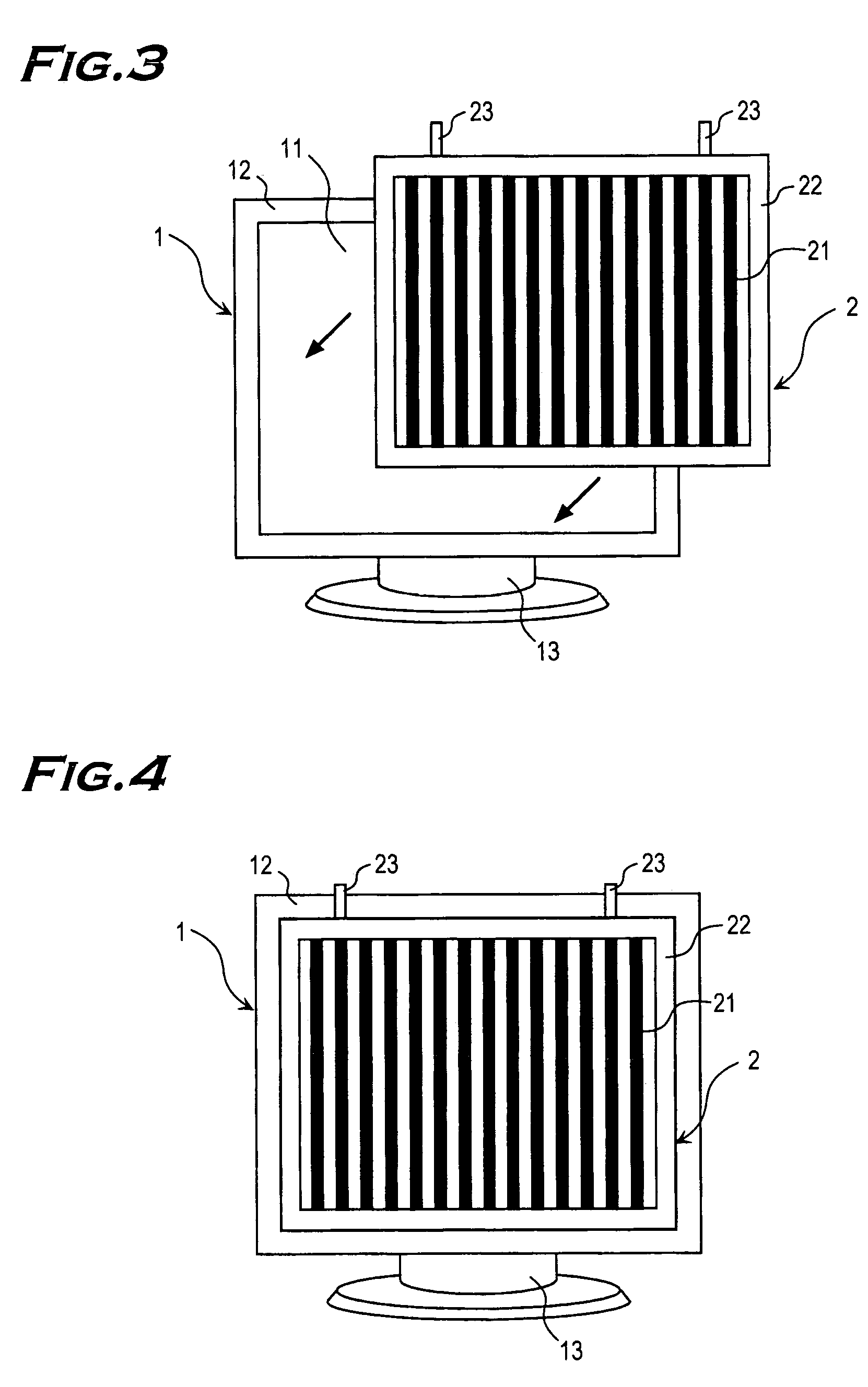
[0190]An image splitter 2 is hanged from the liquid crystal display 1 by fastening members 23c, facing the liquid crystal panel 11. A protruding section is formed on the fastening member 23c to join the parallax barrier substrate 21. The protruding section is inserted into a hole provided on the parallax barrier substrate 21 to join the fastening member 23 and the parallax barrier substrate 21. An end of the protruding section and the parallax barrier substrate 21 are joined to make one plane, without creating steps, on a side of the liquid crystal panel 11. If the parallax barrier substrate 21 and the fastening members 23c may be joined together with an adhesive agent, there is no worry that steps are created on the image splitter 2 on the side of the liquid crystal panel 11.
[0191]After being joined with the fastening member 23c, the image splitter 2 is held in the vicinity of the liquid crystal panel 11 as shown in FIG....
ninth embodiment
[0218]Next, descriptions will be made on an image splitter in the present invention with reference to FIGS. 30 to 36.
[0219]FIG. 30 is a front view of an image splitter in the ninth embodiment of the invention. FIG. 31 is a perspective view of the image splitter in the ninth embodiment of the invention, as seen from the back. FIG. 32 is a front view of the image splitter in the ninth embodiment of the invention. FIG. 33 is a front view showing a state where the image splitter in the ninth embodiment of the invention is being installed to the liquid crystal display. FIG. 34 is a side view showing a state where the image splitter in the ninth embodiment of the invention is installed on the liquid crystal display. FIG. 35 is a cross-sectional view showing a main part of the image splitter in the ninth embodiment of the invention. FIG. 36 is a front view, partly cut away, of a horizontal adjustment mechanism of the image splitter of the invention.
[0220]The image splitter 2 in FIG. 30 com...
PUM
 Abstract
Description
Claims
Application Information