Multimode acoustic imaging in cased wells

a multi-mode acoustic imaging and cased well technology, applied in the direction of instruments, surveys, borehole/well accessories, etc., can solve the problems of environmental and economic undesirable, well non-exploitable, and damage to production equipment,

Active Publication Date: 2009-04-21
SCHLUMBERGER TECH CORP
View PDF6 Cites 17 Cited by
  • Summary
  • Abstract
  • Description
  • Claims
  • Application Information

AI Technical Summary

Benefits of technology

[0048]Other aspects and advantages of the invention will be apparent from the following description and the appended claims.

Problems solved by technology

In particular, migration of water into the oil-producing layer 17 may, in some circumstances, render a well non-exploitable.
Also, migration of oil into the water-bearing layer 19 is environmentally and economically undesirable.
Often, the fracturing process is accompanied by sanding, whereby certain strata of the formation release fine sand that flows through casing perforations into the well, and then up to the surface, where it can damage production equipment.

Method used


Image

  • Multimode acoustic imaging in cased wells
  • Multimode acoustic imaging in cased wells
  • Multimode acoustic imaging in cased wells

Examples


first example embodiment

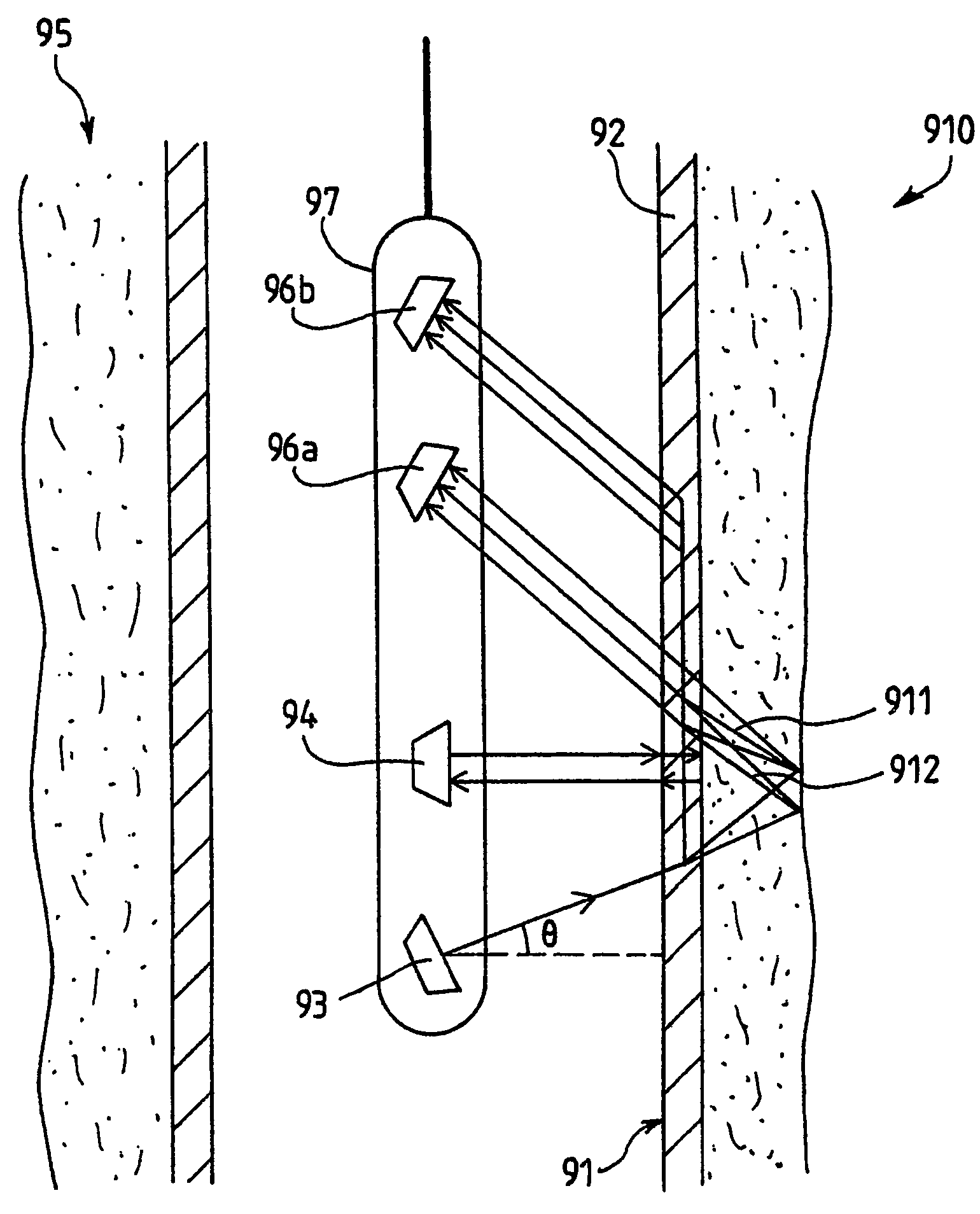
[0084]FIG. 9 contains an illustration of an example apparatus according to the present invention. A description of a zone behind a casing 92 is evaluated by estimating a quality of a fill-material within an annulus between the casing 92 and a formation. A logging tool 97 is provided inside the casing 92 of a well 910. The logging tool 97 comprises a first transducer for transmitting 93 and a second transducer for transmitting 94.

[0085]The logging tool may be moved along a vertical axis inside the casing, and may be rotated around the vertical axis, thus providing an evaluation of the description of the zone behind the casing within a range of depths and azimuthal angles.

[0086]The first transducer for transmitting 93 insonifies the casing 92 with a first acoustic wave. In this example embodiment, the first acoustic wave is emitted with an angle θ relative to a normal of the casing 92 greater than a shear wave critical angle of the first interface 91. Hence the first acoustic wave pro...

second example embodiment

[0115]FIG. 10 illustrates a second example embodiment of the present invention. In this example embodiment, a logging tool 100 comprises an array 101 of transducer elements 102. Each transducer element 102 is able to transmit a signal according to an instruction from a circuit (not represented). By applying delays on the transmitted signals, a steering in a predetermined direction may be possible. At least one first transducer element for transmitting insonifies a casing 103 of a well 104 with a first acoustic wave having a predetermined angle relative to the normal of the casing. The first acoustic wave thus propagates within the casing with a first mode. The first mode may be one of the following modes: extensional, flexural and thickness mode. At least one first transducer element for receiving among the array 101 of transducer elements 102 records a first signal corresponding to the first acoustic wave.

[0116]Similarly, following the recording of the first signal, a second acoust...


PUM


Abstract

A well casing is insonified with a first acoustic wave in a first mode that may be any mode of a set including: extensional mode, thickness mode, flexural mode. A first echo is received at a first acoustic transducer for receiving, a first signal is produced and a first measurement is extracted from the first signal. The casing is then insonified with a second acoustic wave in a second mode that may be any mode of the set of modes but is distinct from the first mode. A second echo is received at a selected second acoustic transducer for receiving and a second signal is produced. A second measurement is extracted from the second signal. The zone behind the casing of the well is evaluated from a combination of the first measurement and the second measurement.

Description

BACKGROUND OF INVENTION[0001]1. Field of the Invention[0002]The invention relates generally to a method and apparatus for acoustical imaging of cased wells.[0003]2. Background Art[0004]In a well completion, a casing or pipe is set in a wellbore, and a fill-material, typically cement, is forced into an annulus between the casing and a formation. The primary purpose of such cement is to separate oil- and gas-producing layers from each other, and from water-bearing strata.[0005]FIG. 1 shows a schematic diagram of a cased well. The cased well generally includes a number of interfaces 121, 122, 123 at junctures of differing materials within a wellbore 11. A “first interface”121 exists at the juncture of a borehole fluid 13 in a casing 14 and the casing 14. The casing 14 is typically made of steel. A “second interface”122 is formed between the casing 14 and an annulus 15 behind the casing 14. If cement 112 is properly placed in the annulus 15, the “second interface”122 exists between the ...

Claims


Application Information

Patent Timeline
Patent Type & Authority Patents(United States)
IPC IPC(8): G01V1/40G01V1/50E21B47/14E21B47/00
CPCE21B47/0005G01V1/50E21B47/005
Inventor FROELICH, BENOITLE CALVEZ, JEAN-LUCLEGENDRE, EMMANUELZEROUG, SMAINE
Owner SCHLUMBERGER TECH CORP
Why Eureka
Try Eureka