Controlled acoustic beam generator for crowd control

a generator and crowd control technology, applied in the field of crowd control means, can solve the problem of extremely undesired use of firearms

Active Publication Date: 2009-04-21
ELECTRO OPTICS RES & DEV
View PDF8 Cites 10 Cited by
  • Summary
  • Abstract
  • Description
  • Claims
  • Application Information

AI Technical Summary

Problems solved by technology

The use of firearms is considered extremely undesired as it inevitably leads to casualties among the crowd and is therefore regarded as highly unacceptable.

Method used


Image

  • Controlled acoustic beam generator for crowd control
  • Controlled acoustic beam generator for crowd control
  • Controlled acoustic beam generator for crowd control

Examples


Embodiment Construction

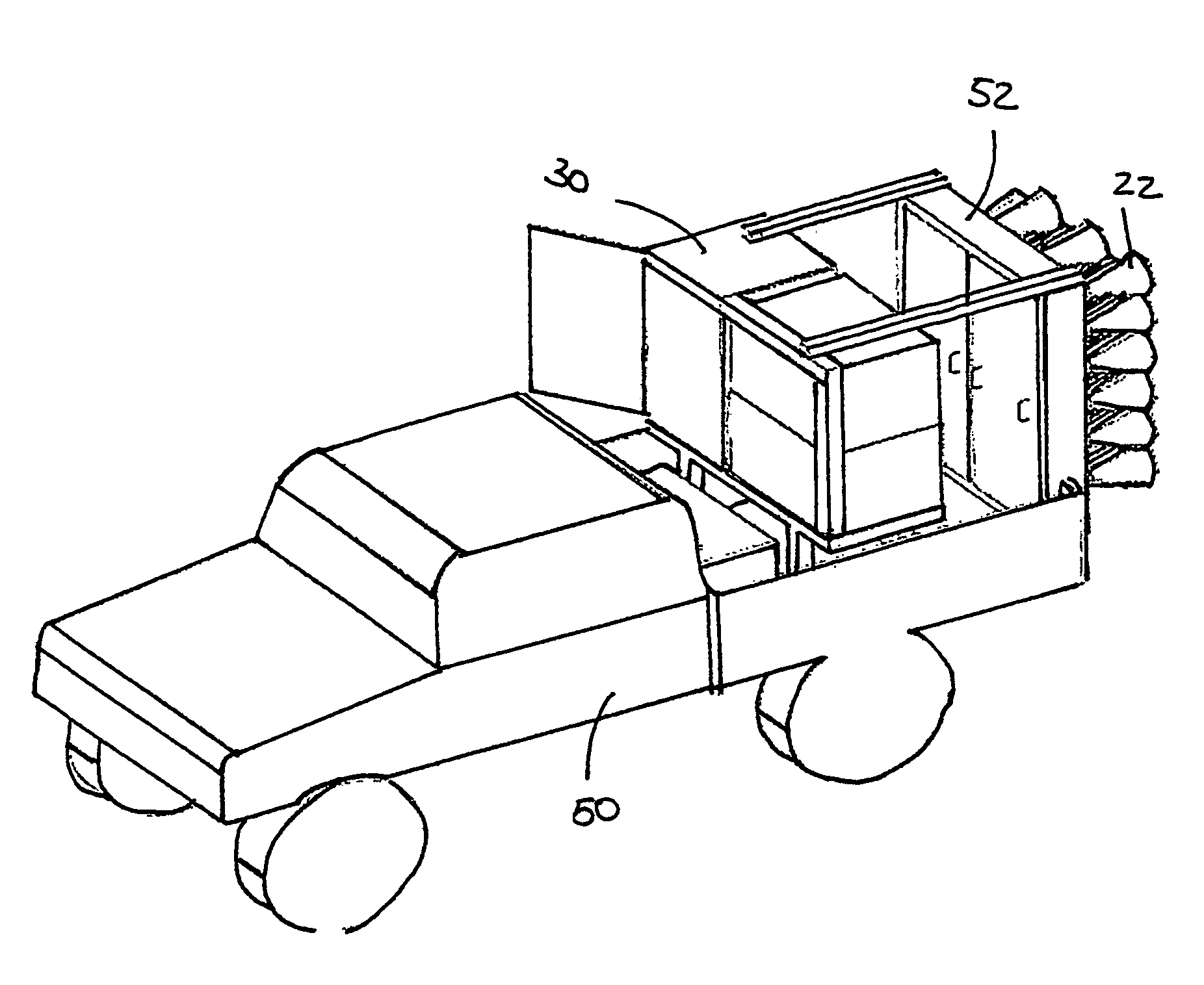
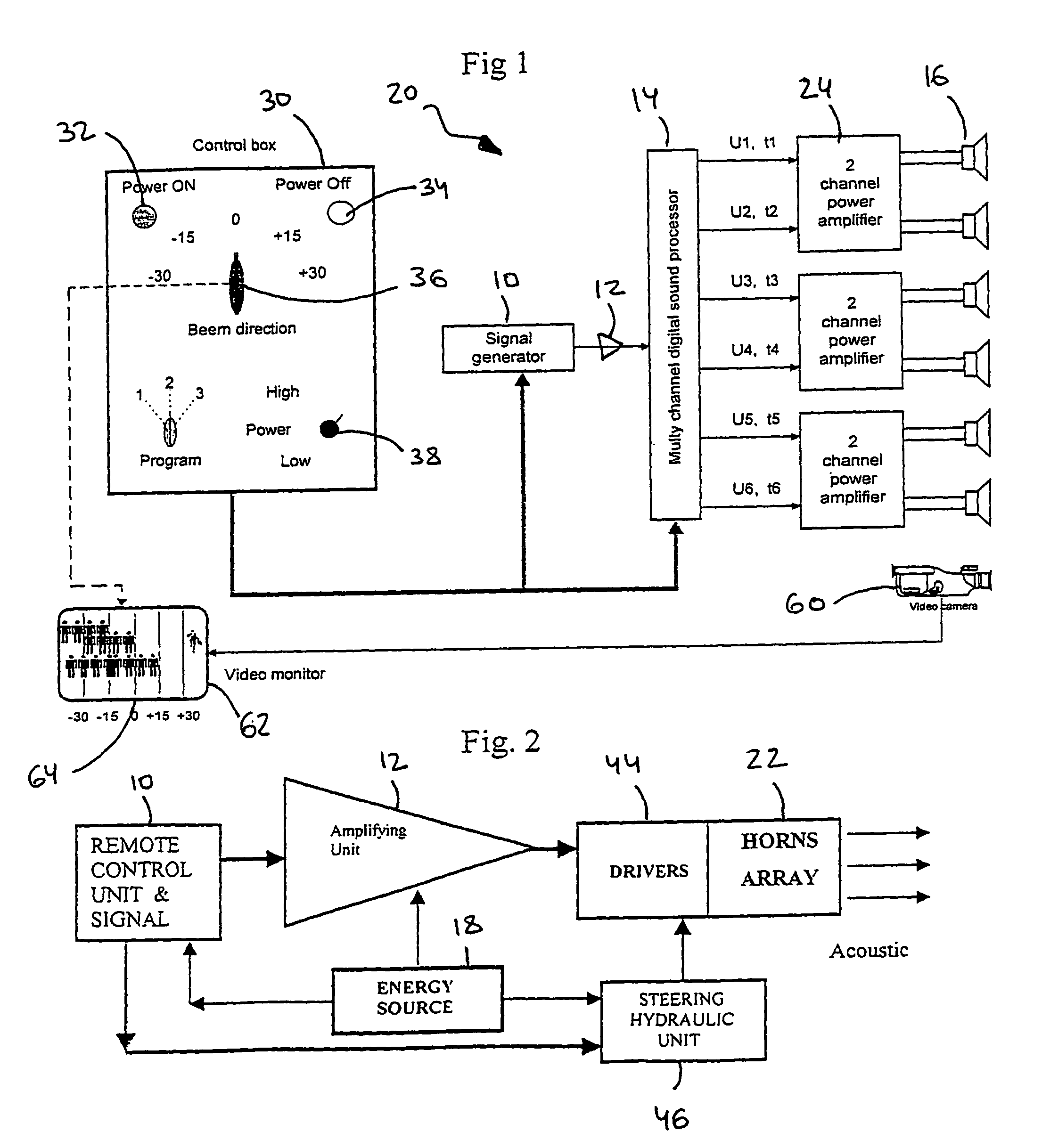
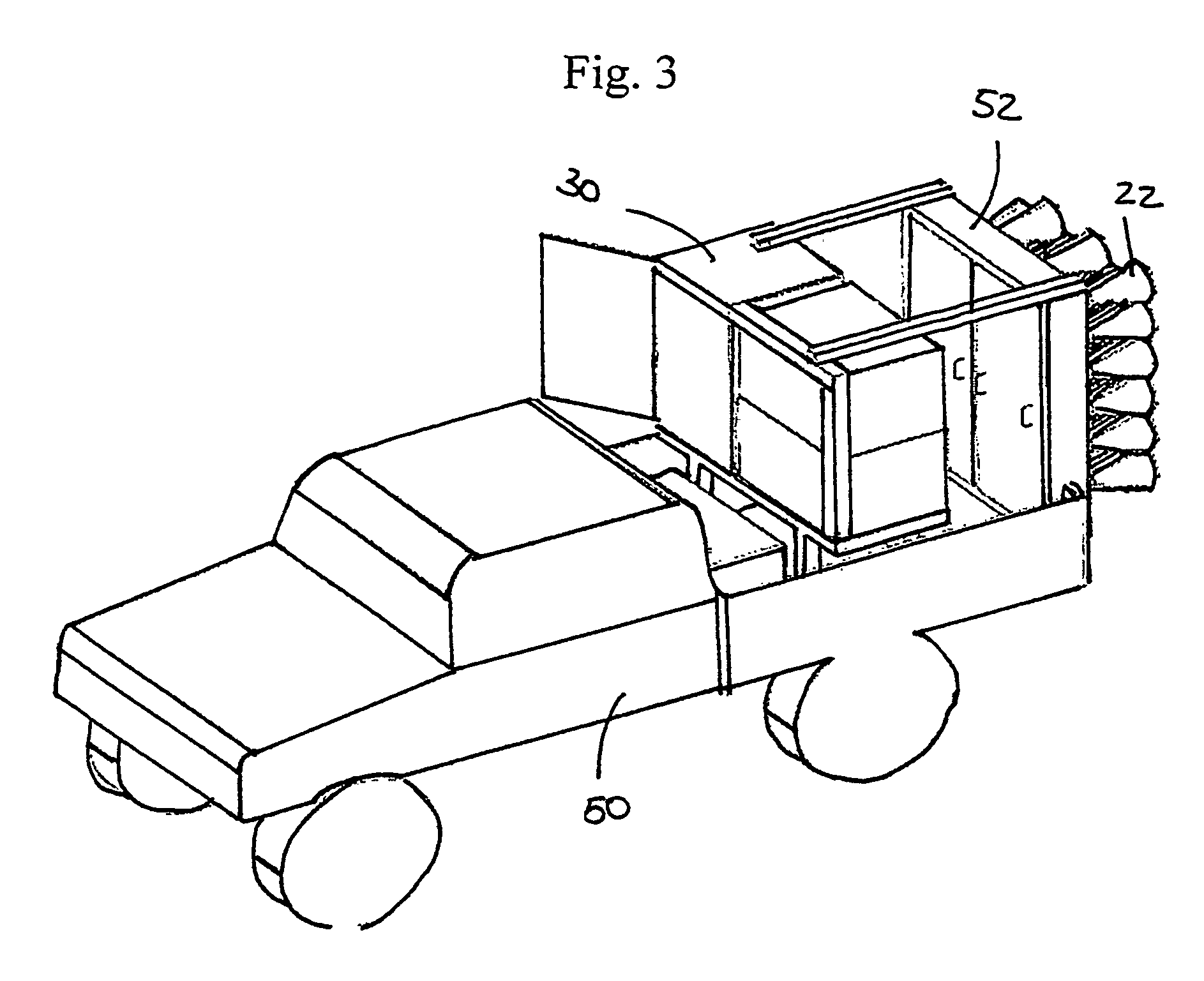
[0053]A main aspect of the present invention is the provision of a high-power acoustic generator system, which produces controlled high power controllable acoustic beam, preferably in, but not limited to, the width range of 8° to 10° (depending on the transmittance frequency). In a preferred embodiment of the present invention the beam can be steered horizontally in a typical sector width of ±45°.

[0054]In order to achieve a controlled acoustic beam an array of acoustic transmitters is used, so as to achieve coherent summation of multiple acoustic transmitters, bearing in mind that when radiation is summed up coherently the power gain is expressed as:

ΔI≈N2I0

[0055]where I0 is the power of a single acoustic transmitter, and N is the number of independent acoustic transmitters used.

[0056]The high-power acoustic generator system of the present invention is to be used as a non-lethal weapon system for riot control and for fending off intruders.

[0057]Another aspect of the present invention...


PUM


Abstract

A controlled acoustic beam generator system comprising: an array of acoustic transmitters; a signal generator, amplifier for amplifying the acoustic signal; multi-channels signal processor, for processing the acoustic signal, distributing corresponding processed acoustic signals, into the array of acoustic transmitters; steering for steering an acoustic beam which is the resultant of transmitted processed signals by the array of acoustic transmitters; and a control unit, for the operation of the system, by controlling the signal generator, the multi-channel signal processor, and the steering.

Description

CROSS-REFERENCE TO RELATED APPLICATIONS[0001]This application is a National Phase Application of PCT International Application No. PCT / IL2004 / 001013, International Filing Date Nov. 4, 2004, claiming priority of IL Patent Application, 158837, filed Nov. 11, 2003.FIELD OF THE INVENTION[0002]The present invention relates to crowd control means. More particularly it relates to non-lethal crowd-control means in the form of high-power controlled acoustic beam generator.BACKGROUND OF THE INVENTION[0003]In many public events, gatherings or riots, police or other law enforcement forces are sometimes forced to use crowd-control means in order to maintain order and prevent chaos. The use of firearms is considered extremely undesired as it inevitably leads to casualties among the crowd and is therefore regarded as highly unacceptable.[0004]Non-lethal crowd-control means were developed to aid law-enforcing forces to maintain order without causing unnecessary injuries or casualties. Among these a...

Claims


Application Information

Patent Timeline
Patent Type & Authority Patents(United States)
IPC IPC(8): H04B1/02A01M29/02G01SG10KG10K15/04H04B1/034
CPCG10K15/04
Inventor ZLOTNIK, ZVIZEILER, EITAN
Owner ELECTRO OPTICS RES & DEV
Why Eureka
Try Eureka