X-ray system, X-ray apparatus, X-ray target, and methods for manufacturing same

a technology of x-ray target and x-ray imaging system, which is applied in the direction of x-ray tube target materials, x-ray tube target and convertor, x-ray tube, etc., can solve the problems of limited thermal conductivity, limited thermo-mechanical properties, and x-ray target produced by the psf method

Active Publication Date: 2009-04-21
GENERAL ELECTRIC CO
View PDF9 Cites 34 Cited by
  • Summary
  • Abstract
  • Description
  • Claims
  • Application Information

AI Technical Summary

Problems solved by technology

X-ray targets produced by the PSF method can be hindered by limited density, density variations, remaining porosity, porosity variations, limited mechanical strength properties, variation of mechanical strength properties, limited thermal conductivity, limited thermo-mechanical properties, limited thermal loading capacity, limited mechanical loading capacity.
X-ray apparatus including X-ray targets having the foregoing limitations are hindered by limited capacity to operate at peak power, limited X-ray target rotation speed, limited gantry rotation speed, limited X-ray output at peak power, limited frequency of exposures at peak power, longer cooling periods between exposures, and limited cycle rate.
The specified limitations of X-ray targets produced by the PSF method can worsen as diameter of the X-ray target increases.
Targets produced by the PSF method can suffer CTE mismatched bending stress or warpage because of differences between material properties of the focal track and the substrate material supporting the focal track.
X-ray targets produced by the PSF method are hindered by the limitation that microstructure of the substrate and focal track materials is not highly controlled and, thus, variations of material properties such as microstructure and variation of microstructure are not optimal and are subject to great variation.

Method used


Image

  • X-ray system, X-ray apparatus, X-ray target, and methods for manufacturing same
  • X-ray system, X-ray apparatus, X-ray target, and methods for manufacturing same
  • X-ray system, X-ray apparatus, X-ray target, and methods for manufacturing same

Examples


Embodiment Construction

[0022]In the following detailed description, reference is made to the accompanying drawings which form a part hereof, and in which is shown by way of illustration specific embodiments which may be practiced. These embodiments are described in sufficient detail to enable those skilled in the art to practice the embodiments and disclosure. It is to be understood that other embodiments may be utilized, and that logical, mechanical, electrical, and other changes may be made without departing from the scope of the embodiments and disclosure. In view of the foregoing, the following detailed description is not to be taken as limiting the scope of the embodiments or disclosure.

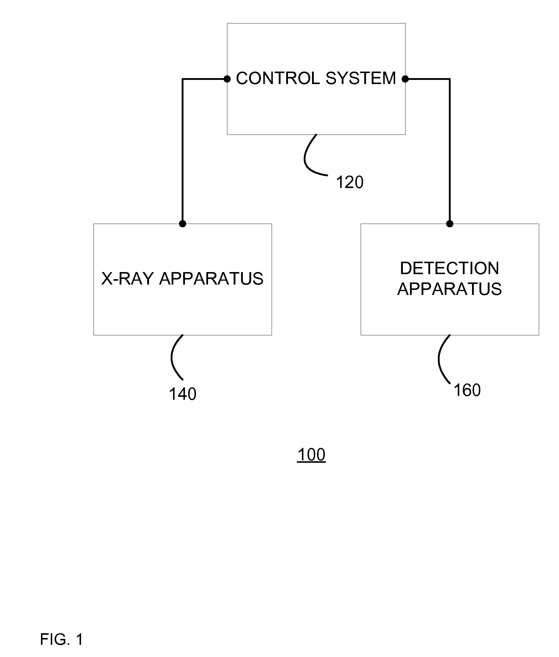
[0023]Illustrated in FIG. 1 is a simplified block diagram of an X-ray imaging system 100 according to an embodiment. It is to be understood that an X-ray imaging system 100 according to embodiments of the disclosure can have different arrangements other than the specific representation illustrated in FIG. 1. One examp...


PUM

PropertyMeasurementUnit
porosityaaaaaaaaaa
timeaaaaaaaaaa
timeaaaaaaaaaa

Abstract

In some embodiments, an X-ray target includes a target cap formed of a substrate material and a focal track layer of emitting material, and at least one of the substrate material and the emitting material has a density greater than about 95.0% of theoretical density. In some embodiments, a method of manufacturing an X-ray target includes forming an intermediate target cap form of substrate material and a focal track layer of emitting material, and compacting the intermediate target cap form by application of gas pressure at elevated temperature to form a final target cap form, and at least the substrate material is dense substrate material having a final density greater than an intermediate density or the emitting material is dense emitting material having a final emitting material density greater than an intermediate emitting material density.

Description

FIELD OF THE INVENTION[0001]The disclosure relates generally to X-ray imaging systems, X-ray apparatus and X-ray targets. The disclosure also relates to methods for manufacturing X-ray systems, X-ray apparatus and X-ray targets.BACKGROUND OF THE INVENTION[0002]X-ray imaging systems typically include an X-ray apparatus operable to generate a beam of X-rays, a detection apparatus, and a control system connected to the X-ray apparatus and detection apparatus. The X-ray apparatus produces a beam of X-rays which interact with a subject and are detected by operation of the detection apparatus. One typical example of an X-ray imaging system is a high performance computed tomography (CT) X-ray imaging system, which accommodates a human subject for medical imaging. Medical X-ray imaging systems typically include a gantry which is movable in relation to the human subject.[0003]X-ray apparatus typically include an X-ray tube which is operable to generate a beam of X-rays. A typical X-ray tube ...

Claims


Application Information

Patent Timeline
Patent Type & Authority Patents(United States)
IPC IPC(8): H01J35/10
CPCH01J35/108B22F3/02B22F3/10B22F2998/10H01J2235/081H01J2235/085
Inventor STEINLAGE, GREGORY ALANTIEARNEY, JR., THOMAS CARSONHEBERT, MICHAEL SCOTTSIEMERS, PAUL ALFREDROGERS, KIRK ALANHENRICHSEN, RAY ALDEN
Owner GENERAL ELECTRIC CO
Why Eureka
Try Eureka