Equipment service vehicle having on-board diagnostic system

a technology for equipment service vehicles and diagnostic systems, which is applied in the direction of instruments, structural/machine measurement, transportation and packaging, etc., can solve the problems of increasing complexity and difficulty in maintenance of modern vehicles, increasing the cost of approach implementation, and not being widely availabl

Inactive Publication Date: 2009-04-21
OSHKOSH CORPORATION
View PDF273 Cites 128 Cited by
  • Summary
  • Abstract
  • Description
  • Claims
  • Application Information

AI Technical Summary

Benefits of technology

[0009]According to a first preferred embodiment, an equipment service vehicle comprises a network communication link, a plurality of vehicle subsystems, a test control module, and an operator interface. Each vehicle subsystem comprises a mechanical system and an electronic control system that controls the mechanical system. Each respective electronic control system is connected to the network communication link and transmits information pertaining to the health and operation of the mechanical system on the network communication link. The test control module is mounted on board the vehicle and is coupled to the plurality of vehicle subsystems by way of the network comm...

Problems solved by technology

Modern vehicles have become increasingly complex and difficult to maintain.
When a malfunction is not properly diagnosed, the result is typically that parts which are fully operational are repaired or replaced, that parts which are repairable are replaced, and/or that parts which are not fully operational are not repaired or replaced.
First, this approach is expensive to implement because it requires numerous sensors above and beyond those required for normal operation of the vehicle.
Additionally, the required sensors typically have unique signal characteristics that are specifically matched to the diagnostic equipment, and therefore the sensors are specialty items that are more expensive and not commonly available.
Second, this approach results in a diagnostic system with an unduly limited capability to accurately diagnose system faults.
The capabilities of the diagnostic system are limited by the fa...

Method used


Image

  • Equipment service vehicle having on-board diagnostic system
  • Equipment service vehicle having on-board diagnostic system
  • Equipment service vehicle having on-board diagnostic system

Examples


Embodiment Construction

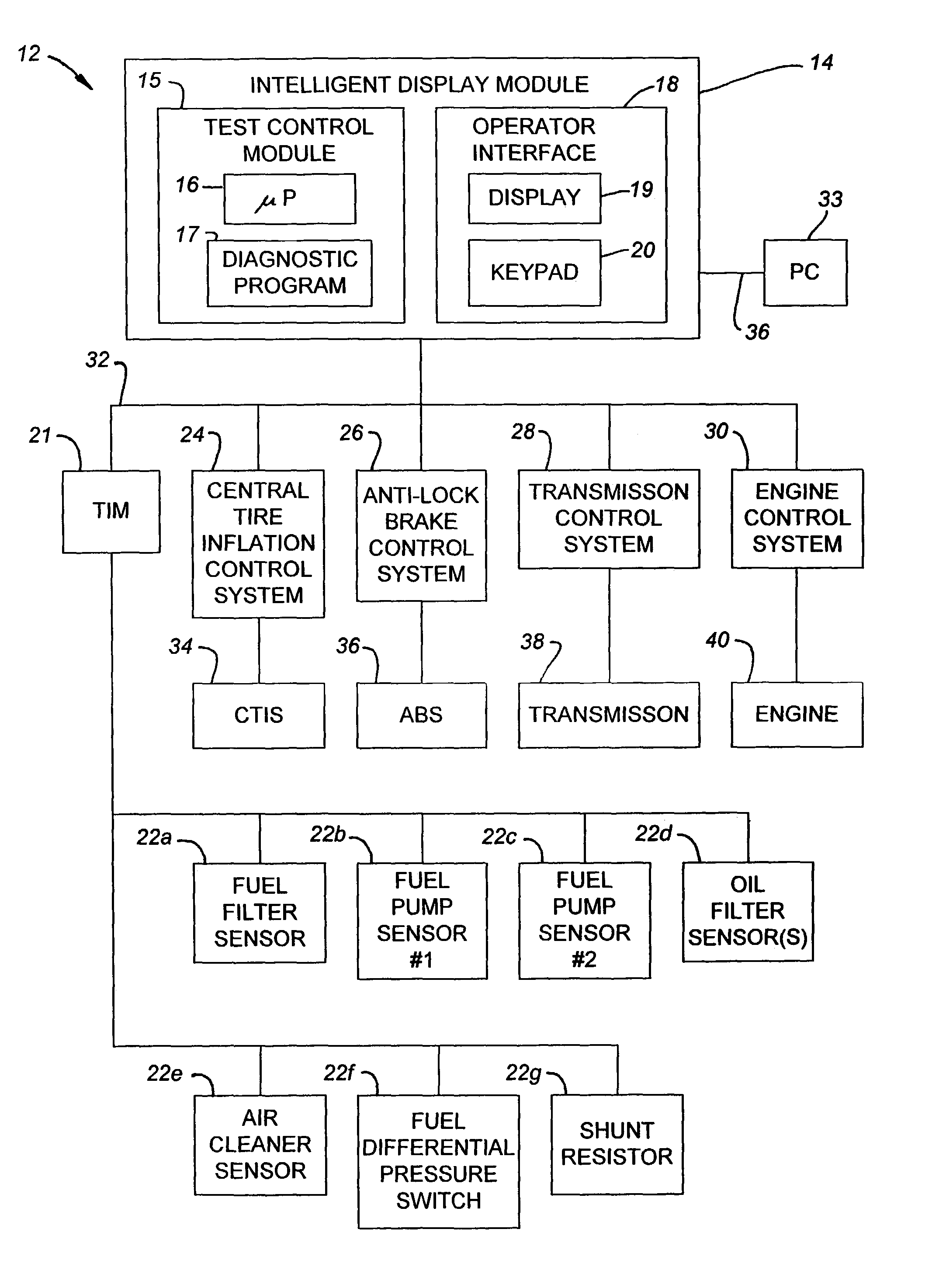
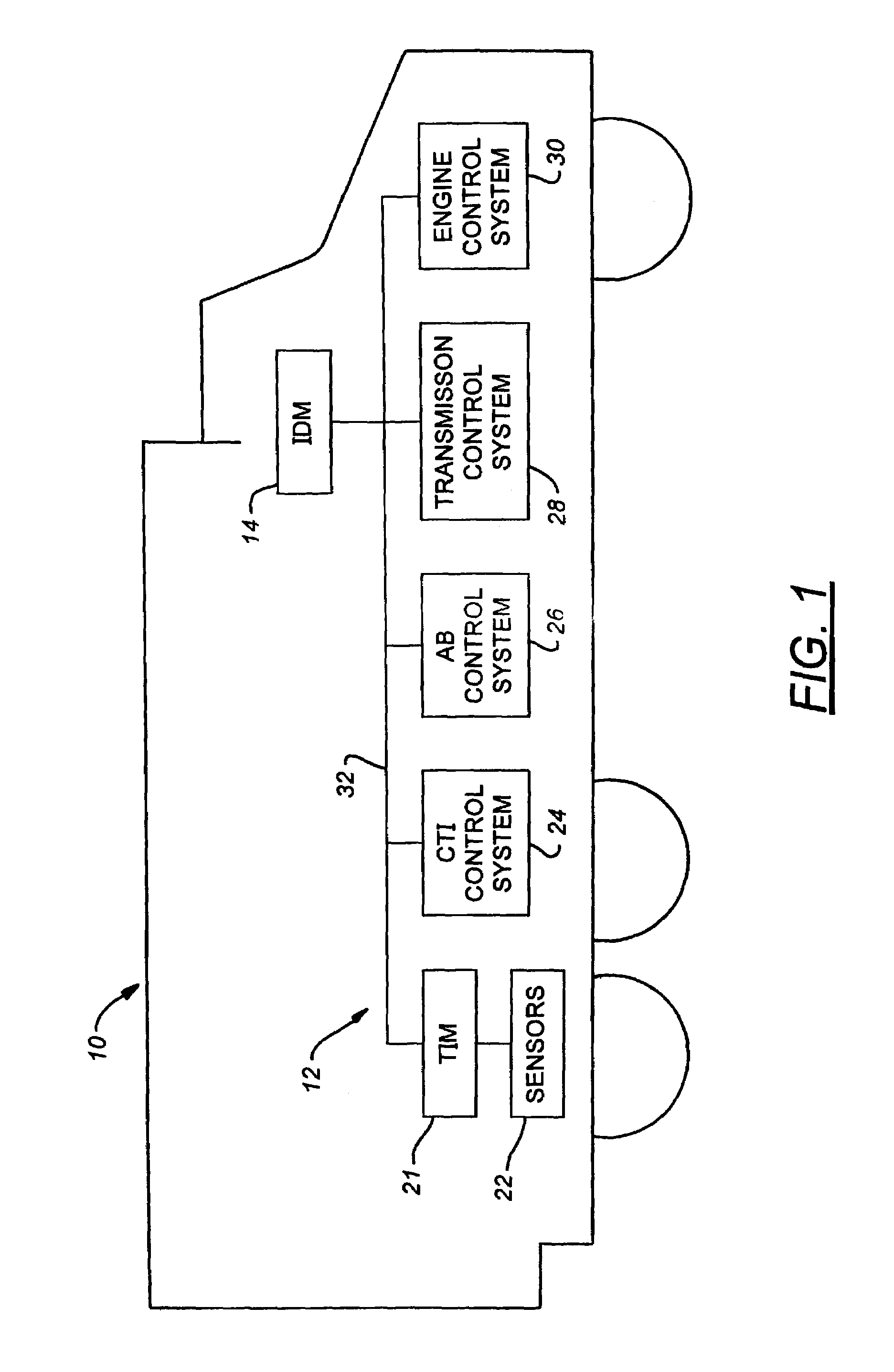
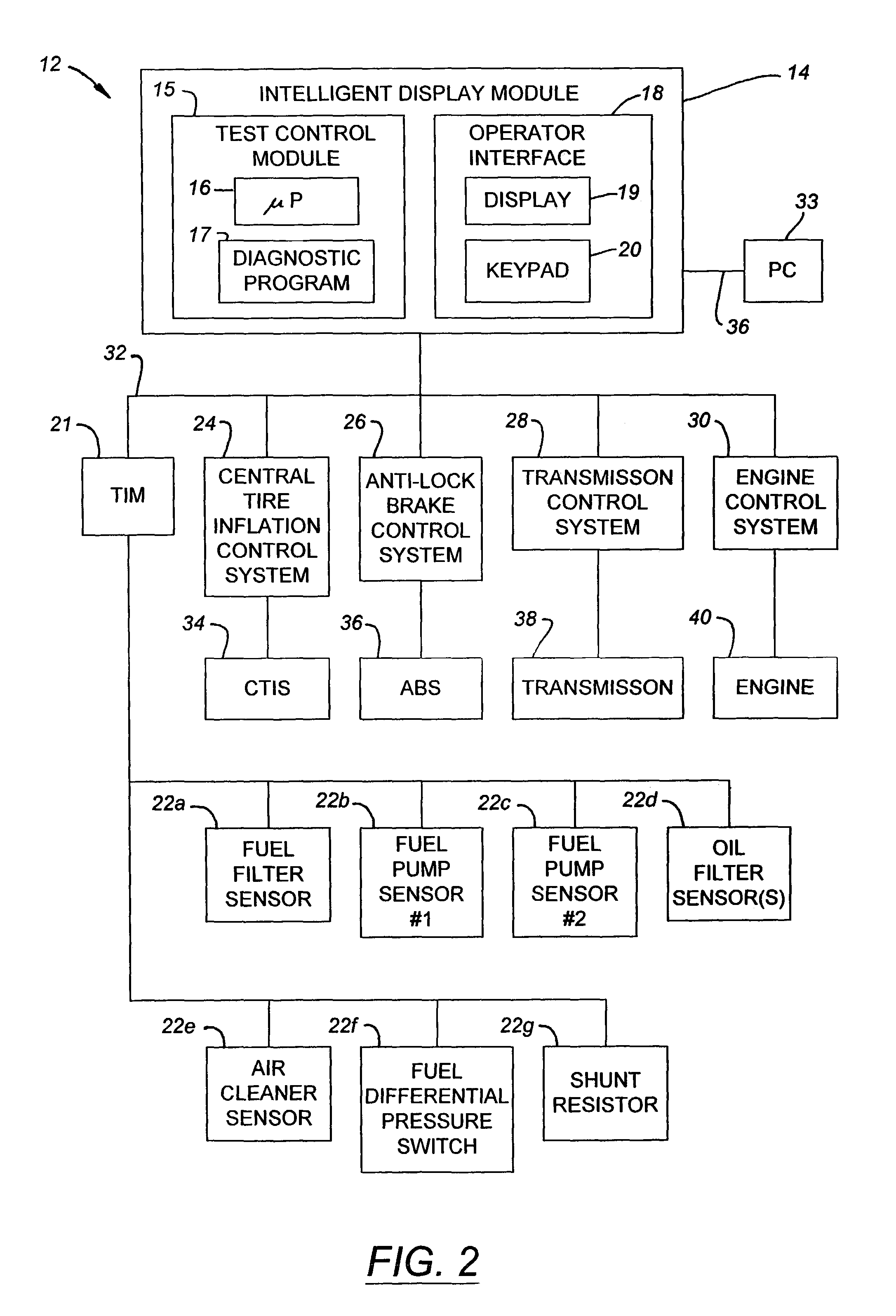
[0020]Referring now to FIG. 1, a preferred embodiment of an equipment service vehicle 10 having a diagnostic system 12 according to an embodiment of the invention is illustrated. By way of overview, the diagnostic system 12 comprises an intelligent display module 14, a test interface module 21 connected to a plurality of sensors 22, and a plurality of additional vehicle control systems 24–30. The intelligent display module 14, the test interface module 21, and the plurality of additional vehicle control systems 24–30 are interconnected with each other by way of a network communication link 32.

[0021]More specifically, the vehicle 10 is a military vehicle and, in particular, a medium tactical vehicle. However, it should be understood that the diagnostic system 12 of FIG. 1 could also be used with other types of military vehicles. For example, the diagnostic system 12 could be used in connection with heavy equipment transporter vehicles, which are used to transport battle tanks, fighti...


PUM


Abstract

An equipment service vehicle comprises a network communication link, a plurality of vehicle subsystems, a test control module, and an operator interface. The test control module is mounted on board the vehicle and is coupled to the plurality of vehicle subsystems by way of the network communication link. The test control module is programmed to acquire at least some of the information pertaining to the health and operation of a mechanical system. The operator interface is mounted on board the vehicle and is coupled to the test control module. The operator interface comprises a display that displays a menu of test options to an operator and an input device that receives an operator input indicative of a menu selection made by the operator. At least some of the information pertaining to the health and operation is displayed to the operator.

Description

CROSS-REFERENCE TO RELATED APPLICATION[0001]This application is a continuation of U.S. Ser. No. 09 / 500,506, filed Feb. 9, 2000, now U.S. Pat. No. 6,553,290, issued Apr. 22, 2003, hereby incorporated by reference.FIELD OF THE INVENTION[0002]This invention relates to diagnostic systems for equipment service vehicles. In particular, this invention relates to an on-board diagnostic system for equipment service vehicles.DESCRIPTION OF RELATED ART[0003]Modern vehicles have become increasingly complex and difficult to maintain. In order to enable more efficient vehicle maintenance, it is desirable to be able to accurately diagnose malfunctioning subsystems, such as engine systems, transmission systems, and so on, as well as specific vehicle components. When a malfunction is not properly diagnosed, the result is typically that parts which are fully operational are repaired or replaced, that parts which are repairable are replaced, and / or that parts which are not fully operational are not re...

Claims


Application Information

Patent Timeline
IPC IPC(8): G01M17/00B60Q1/00G07C5/00G07C5/08
CPCG01M17/00G07C5/008G07C5/085
Inventor PILLAR, DUANE R.
Owner OSHKOSH CORPORATION
Why Eureka
Try Eureka