Weld gun lug resurfacing tool

a technology for resurfacing tools and weld gun arms, which is applied in the direction of manufacturing tools, portable lathes, wood boring tools, etc., can solve the problems of undesirable replacement, high cost of replacement gun arms, and arcing of cable lugs, so as to avoid disassembly and replacement, reduce the cost of a new weld gun arm, and minimize downtime

Inactive Publication Date: 2009-04-28
GM GLOBAL TECH OPERATIONS LLC
View PDF7 Cites 2 Cited by
  • Summary
  • Abstract
  • Description
  • Claims
  • Application Information

AI Technical Summary

Benefits of technology

[0007]An advantage of an embodiment is that a quick and environmentally-friendly tool and method for resurfacing the lug face on a cable lug of weld gun arms is provided. Disassembly and reassembly of the weld gun is not required since the resurfacing tool is small enough to be used without disassembling the gun, thus minimizing downtime. Also, grinding and sanding is avoided in order to eliminate dust from the copper beryllium alloy, and the copper beryllium chips taken from the lug face are captured for proper disposal. Moreover, the cost of a new weld gun arm and downtime for disassembly and replacement is avoided. And, the resurfacing tool can be driven by a common source of rotary power, such as, for example, a common drill.

Problems solved by technology

If a jumper cable loosens-up during operation of the weld gun, the arcing that occurs at the joint between the cable lug and the jumper cable (gun arm cable) can cause the cable lug to become arced (burned).
Replacement is undesirable because of the down time for disassembly and reassembly of the weld gun components, as well as the relatively high cost of the replacement gun arms.
Grinding or sanding the lug face of the cable lug is undesirable because of the environmental considerations involved with dust from the copper beryllium alloy that the cable lugs are typically cast from.
Providing for an environmentally-controlled area for machining the lug face has the drawbacks of having to set up an environmentally-controlled area, and also the downtime required for disassembly and reassembly of the gun in order to be able to take the cable lug to this area for processing.

Method used


Image

  • Weld gun lug resurfacing tool
  • Weld gun lug resurfacing tool
  • Weld gun lug resurfacing tool

Examples


Embodiment Construction

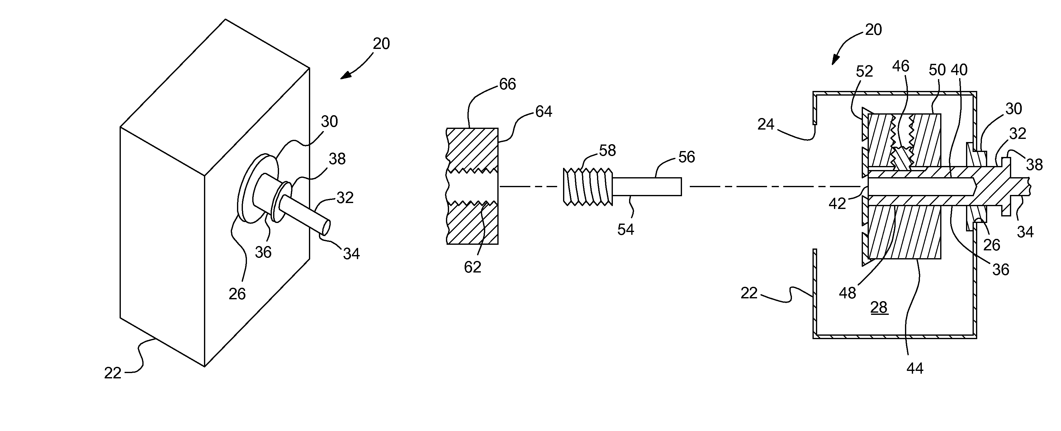
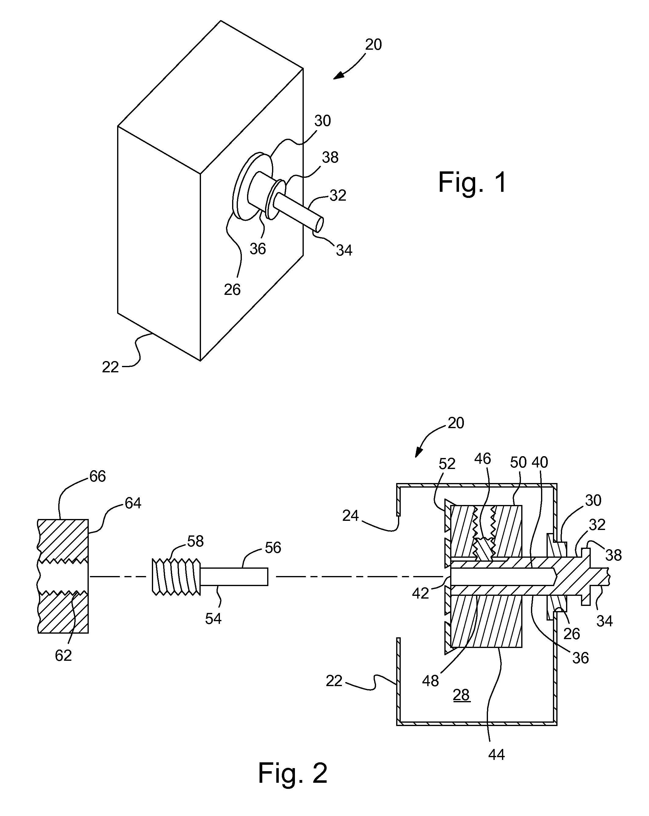
[0015]FIGS. 1-2 illustrate a resurfacing tool, indicated generally at 20. The resurfacing tool 20 includes a hollow chip retention housing 22 having a lug entrance 24, a bushing opening 26 and a chip retention area 28. A bushing 30 is mounted in the bushing opening 26 and receives and supports a rotary tool attachment shaft 32 for rotary motion.

[0016]The rotary attachment shaft 32 includes a rotary tool attachment portion 34 that is sized to be readily connected to a source of rotary power, such as, for example, a handheld drill (not shown). A telescoping portion 36 extends from the attachment portion 34 and extends through the bushing 30 into the housing 22. The telescoping portion 36 can both slide axially and rotate relative to the bushing 30. A travel limit flange 38 extends radially outward between the attachment portion 34 and the telescoping portion 36 to limit the extent of travel of the rotary attachment shaft 32 into the housing 22. An alignment bore 40 extends axially int...


PUM

PropertyMeasurementUnit
areaaaaaaaaaaa
rotary poweraaaaaaaaaa
electrical alignmentaaaaaaaaaa

Abstract

A resurfacing tool and method of operation for a weld gun lug having a lug face is disclosed. The resurfacing tool may comprise a hollow chip retention housing having a lug entrance, a bushing opening, and a chip retention area. A rotary attachment shaft extends through the lug entrance and rotates relative to the retention housing, driven by a rotary power tool. A cutting head assembly is mounted to the rotary attachment shaft in the retention housing for rotation with the rotary attachment shaft, with the cutting head assembly having a cutting head facing toward the lug entrance. A member defines an alignment bore oriented coaxially relative to the rotary attachment shaft. A guide pin has a lug attachment portion configured to attach to the weld gun lug normal to the cable bolt attachment hole, and a pilot shaft telescopically received in the alignment bore.

Description

BACKGROUND OF INVENTION[0001]The present invention relates generally to a resurfacing tool for welding equipment.[0002]For particular welding systems, weld gun arms may include cable lugs that attached to jumper cables. The face of the lug adjacent to the jumper cable must be kept perpendicular to a cable bolt attachment hole for proper electrical alignment—that is, in order to avoid arcing during operation of the weld gun. If a jumper cable loosens-up during operation of the weld gun, the arcing that occurs at the joint between the cable lug and the jumper cable (gun arm cable) can cause the cable lug to become arced (burned).[0003]Once damaged, the weld gun arm cable lug must be repaired or replaced. Replacement is undesirable because of the down time for disassembly and reassembly of the weld gun components, as well as the relatively high cost of the replacement gun arms. Grinding or sanding the lug face of the cable lug is undesirable because of the environmental considerations ...

Claims


Application Information

Patent Timeline
Patent Type & Authority Patents(United States)
IPC IPC(8): B23B5/16B23B3/22
CPCB23B5/168B23Q11/0053Y10T407/1946Y10T407/1908Y10T82/22Y10T82/10Y10T407/1948Y10T408/03Y10T408/89
Inventor HENSLEY, MICHAEL E.CLEGG, BLAKE L.WARE, DOUGLAS W.DANIELS, RANDY E.SCHOCH, ROBERT W.DECKER, RANDALL H.
Owner GM GLOBAL TECH OPERATIONS LLC
Why Eureka
Try Eureka