Device for supporting and vertically adjusting the position of an object upon a support structure

a support device and vertical adjustment technology, applied in the direction of machine supports, couplings, rod connections, etc., can solve the problems of adding damage to the wall, object must be removed from the wall, and relatively long and unsightly wires exposed to the viewer

Inactive Publication Date: 2009-04-28
EAZYPOWER CORP
View PDF21 Cites 6 Cited by
  • Summary
  • Abstract
  • Description
  • Claims
  • Application Information

AI Technical Summary

Benefits of technology

[0006]It is an object of the present invention to overcome many of the disadvantages associated with devices for supporting and vertically adjusting the position of an object after the device is secured to a support structure.
[0007]A principle object of the present invention is to provide a device that promotes vertical adjustment of an object such as a picture or mirror upon a wall after the device, with the object secured thereto, has been secured to the wall without adding fasteners to the device once a vertical elevation for the object has been selected. A feature of the device is two slidably joined members, a first member being attached to the wall, a second member being vertically adjustable relative to the first member. An advantage of the device is that the elevation of the second member is maintained by securing the second member to the first member. Another advantage of the device is that the elevation of the second member is maintained without securing the second member to the wall.
[0008]Another object of the present invention is to provide a device that does not damage a wall that the device is attached to. A feature of the device is that the only items that penetrate the wall are the fasteners that secure a first member of the device to the wall. An advantage of the device is that the elevation of an object secured to a second member of the device, may be incrementally adjusted and evaluated without further damage to the wall.

Problems solved by technology

The problem with these patents is that the object must be removed from the wall to rotate the adjusting screws to reposition the object.
The problem with the Rushing patent is that a relatively large baseplate must be used together with a threaded bolt and nut that are loosened and locked (upon removing the object) to repeatedly adjust the vertical position of the object.
The problem with the Fleishman patent is that relatively long and unsightly wires are exposed to the viewer gazing upon the object.
The problem with the Goss patent is that after securing a first member to a wall, a second member that supports the object must also be secured to the wall to maintain the vertical position of the object thereby causing added damage to the wall each time the vertical position of the object is adjusted.

Method used


Image

  • Device for supporting and vertically adjusting the position of an object upon a support structure
  • Device for supporting and vertically adjusting the position of an object upon a support structure
  • Device for supporting and vertically adjusting the position of an object upon a support structure

Examples


Embodiment Construction

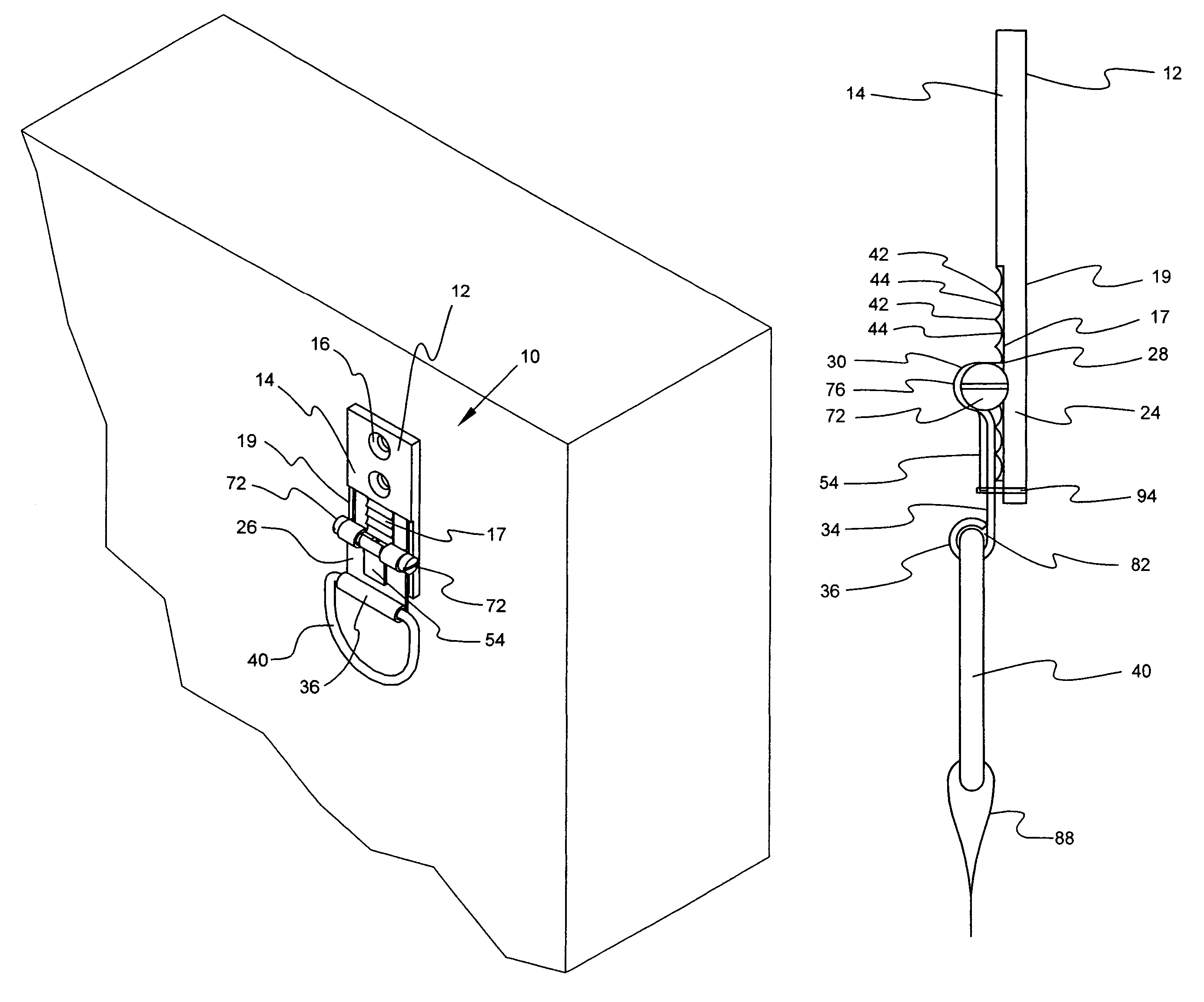
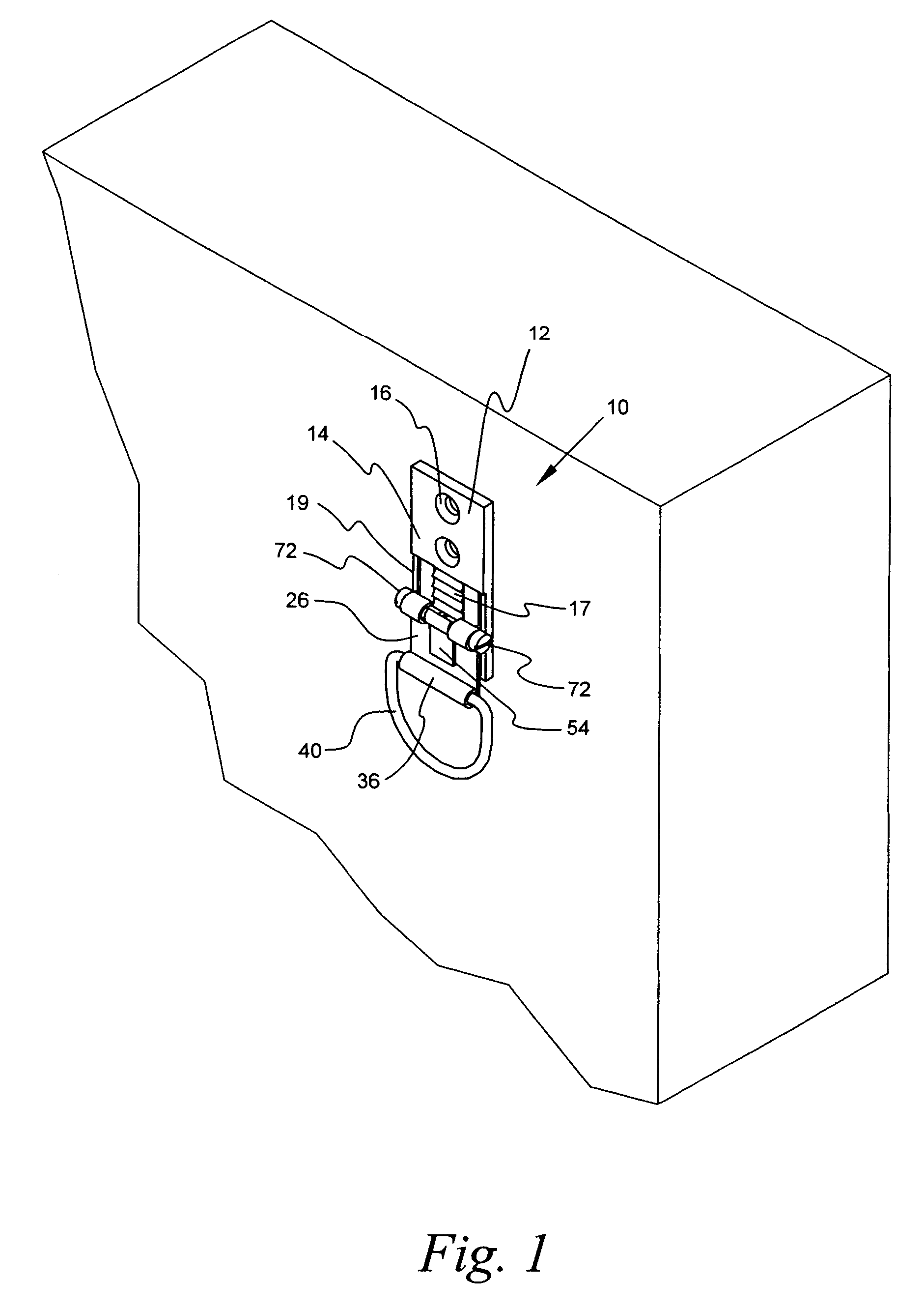
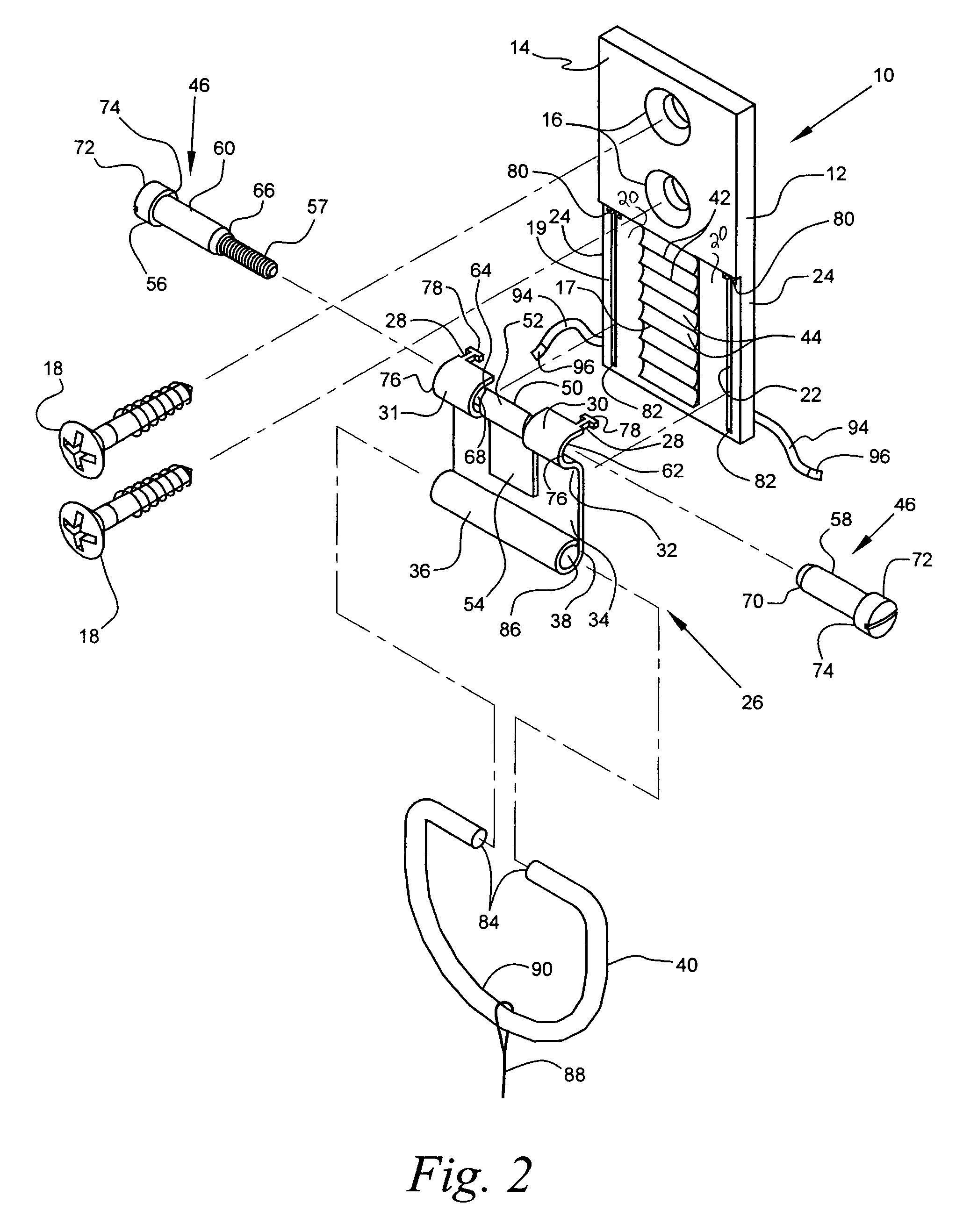
[0029]Referring now to the drawings, a device for supporting and vertically adjusting the position of a picture or other object (not depicted) after the device is secured to a support structure is denoted by numeral 10. The device 10 is fabricated from carbon steel and includes a first or corrugated member 12 having a substantially rectangular configuration with an upper portion 14 with two apertures 16 therethrough to receive fasteners 18 (preferably flathead woodscrews) that secure the first member 12 to a wall or similar support structure. The first member 12 includes a corrugated surface 17 formed in a planar wall 20 of a lower portion 19 between channels 22 formed in opposing edge portions 24 of the lower portion 19. The device 10 further includes an object supporting second member 26 that is slidably and removably secured to the first member 12 via skate members 28 inserted in the channels 22 of the first member 12 to ultimately adjust the vertical position of the object after...


PUM


Abstract

A device 10 for supporting and vertically adjusting the position of a picture or other object after the device 10 is secured to a support structure includes a first member 12 having an upper portion 14 that is secured to a wall or similar support structure, and a lower portion having a plurality of horizontally aligned and alternating ridges 42 and parallel arcuate depressions 44 that are adjacent and perpendicular to opposing vertical channels 22. The device further includes a second member 26 that is slidably secured to the first member 12 via skate members 28 inserted in the channels 22 of the first member 12. An annular hanger member 36 is joined to a lower end 38 of the plate portion 34 to removably receive a substantially “D” configured hanger 40 that supports the object. A locking rod 46 is ultimately inserted between the first and second members 12 and 26 such that the vertical position of the second member 26 and the object secured thereto is maintained without inserting fasteners through the second member 26 and into the support structure.

Description

BACKGROUND OF THE INVENTION[0001]1. Field of the Invention[0002]The present invention relates to vertically adjustable support devices for positioning a painting or mirror upon a wall or other support structure and more particularly, to a device that adjusts the position of the object after a first or support member of the device has been secured to the wall, the device vertically positioning the object via a second member without fastening the second member to the wall thereby minimizing wall damage.[0003]2. Background of the Prior Art[0004]A plethora of wall mounted adjustable support devices are available for vertically adjusting pictures, paintings, mirrors or like objects upon a wall. The devices include adjusting screws that vertically position the object upon the wall as disclosed in U.S. Pat. No. 5,931,439 (Lemire) and U.S. Pat. No. 6,062,525 (Lemire). The problem with these patents is that the object must be removed from the wall to rotate the adjusting screws to reposition...

Claims


Application Information

Patent Timeline
Patent Type & Authority Patents(United States)
IPC IPC(8): F16B45/00
CPCF16B45/00Y10T24/3991Y10T403/32229Y10T403/32131F16B45/002
Inventor KOZAK, BURTONSEMEL, CHARLES
Owner EAZYPOWER CORP
Why Eureka
Try Eureka