

Mitigation of array factor distortions for GPS and broadband reception
- Summary
- Abstract
- Description
- Claims
- Application Information
AI Technical Summary
Benefits of technology
Problems solved by technology
Method used
Image

Examples
Embodiment Construction
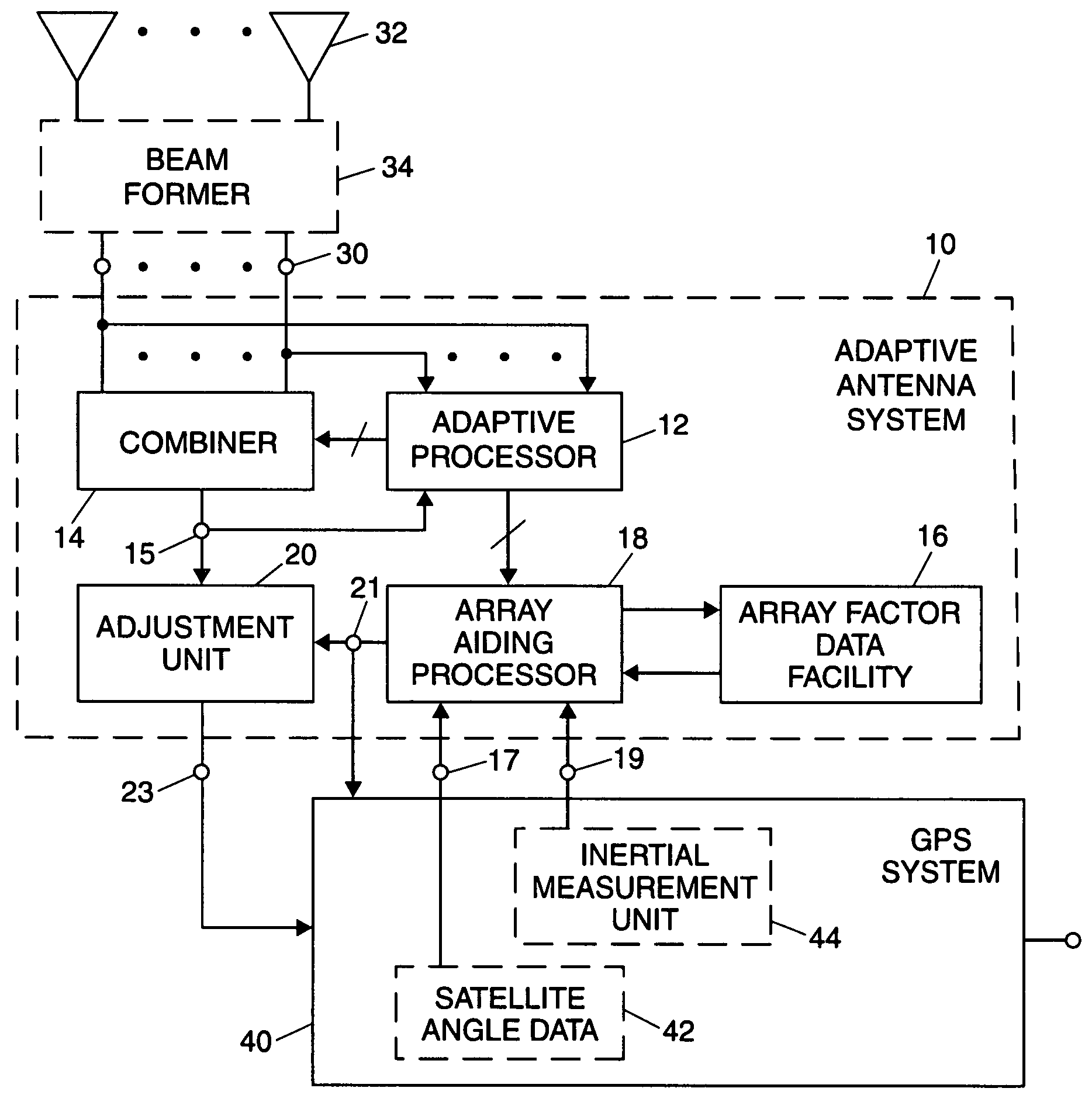
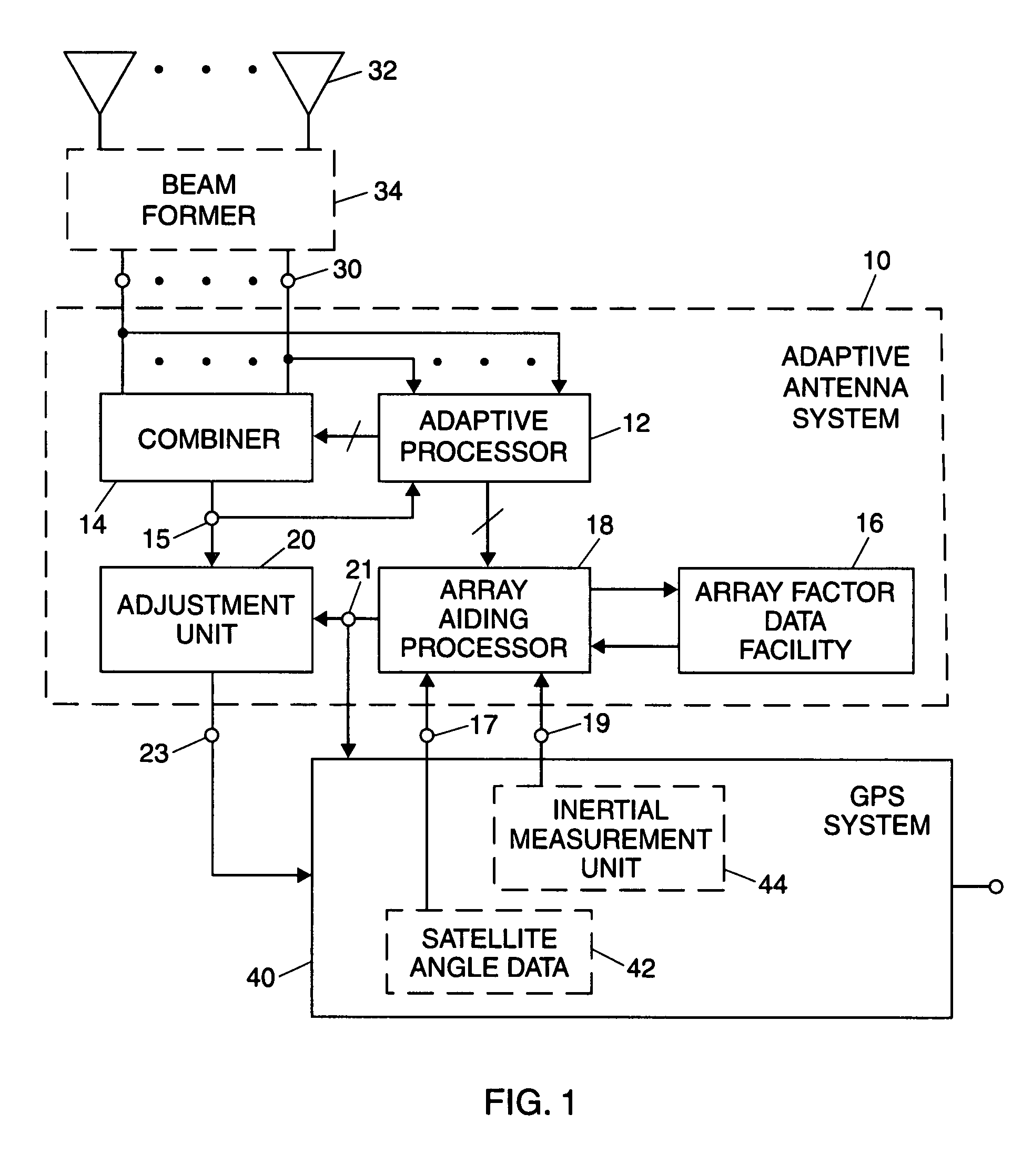
[0021]FIG. 1 is a simplified block diagram of an embodiment of an adaptive antenna system 10, which may be used with a GPS system 40. As will be described, adaptive antenna system 10 is arranged to operate with array factor mitigation to reduce effects of reception characteristic variations (array factor distortions) associated with reception of GPS signals via an adapted antenna pattern of the type discussed above.
[0022]As illustrated, adaptive antenna system 10 includes a plurality of input ports, a representative one of which is shown at 30. The input ports are coupled to an array antenna including a plurality of radiating elements, a representative one of which is shown at 32. In a presently preferred arrangement, the input ports represented by port 30 are each coupled to one of the radiating elements represented by element 32, directly or via any suitable coupling arrangement which may be provided by skilled persons. In some applications it may be appropriate to couple incoming...
PUM
 Abstract
Description
Claims
Application Information