Surface inspection system using laser line illumination with two dimensional imaging

a surface inspection and laser line technology, applied in the field of surface inspection systems, can solve the problems of limited illumination lines, surface inspection tools are limited by the capabilities of surface inspection tools, and the sensitivity of surface inspection tools are particularly susceptible to the effect of sensitivity

Active Publication Date: 2009-04-28
KLA TENCOR TECH CORP
View PDF2 Cites 244 Cited by
  • Summary
  • Abstract
  • Description
  • Claims
  • Application Information

AI Technical Summary

Problems solved by technology

Objects which may be particularly susceptible to surface inspection tool sensitivity are semiconductor wafers.
In some cases, however, the width of an illumination line may be limited by the capabilities of the s

Method used


Image

  • Surface inspection system using laser line illumination with two dimensional imaging
  • Surface inspection system using laser line illumination with two dimensional imaging
  • Surface inspection system using laser line illumination with two dimensional imaging

Examples


Embodiment Construction

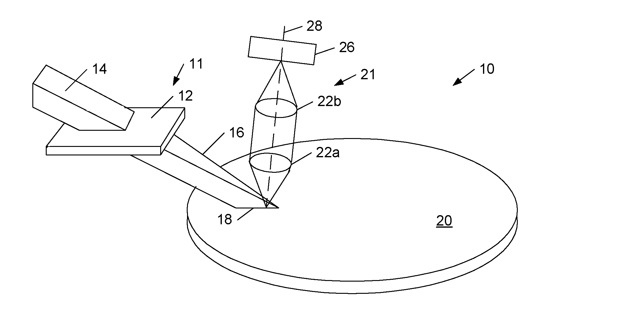
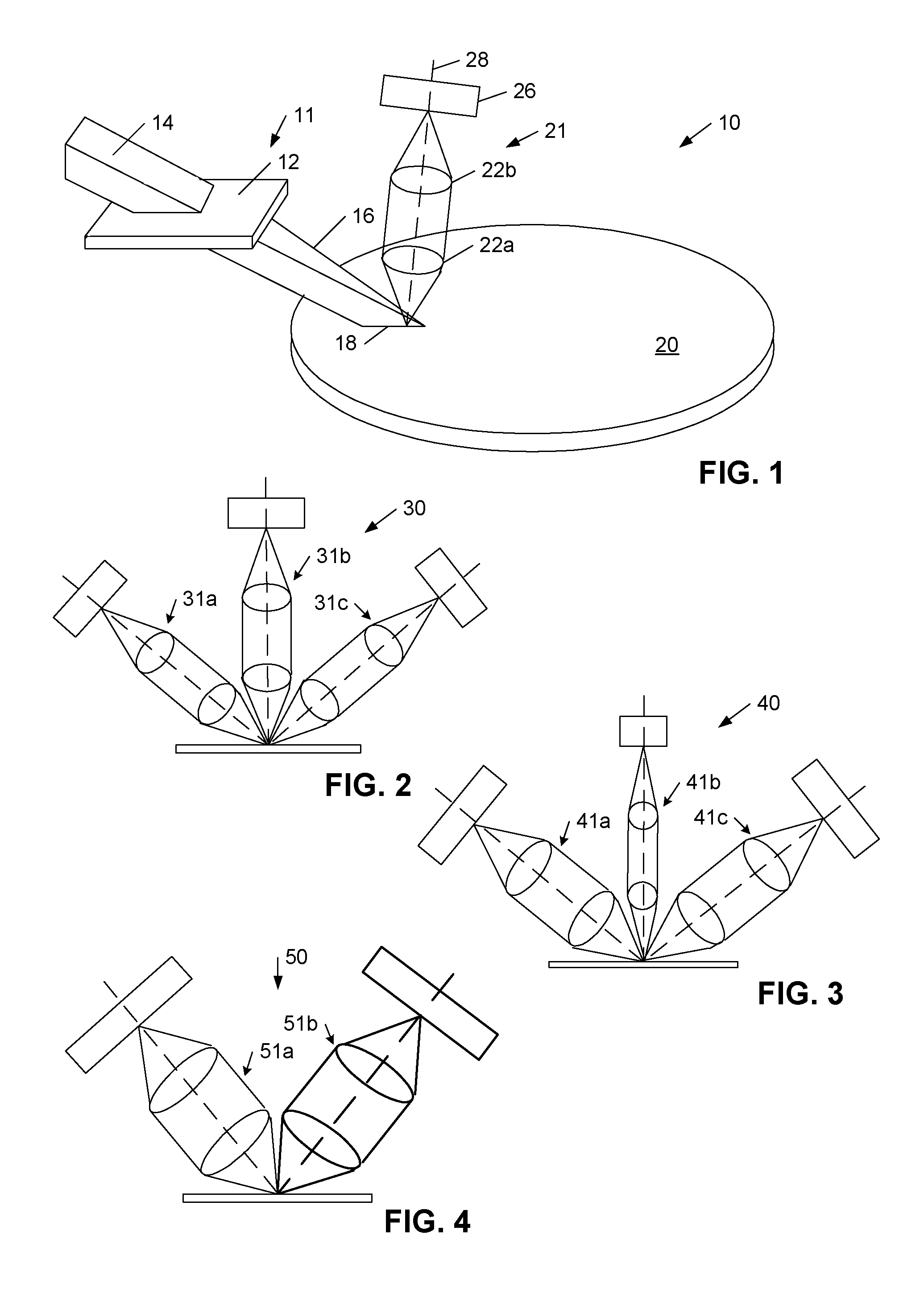
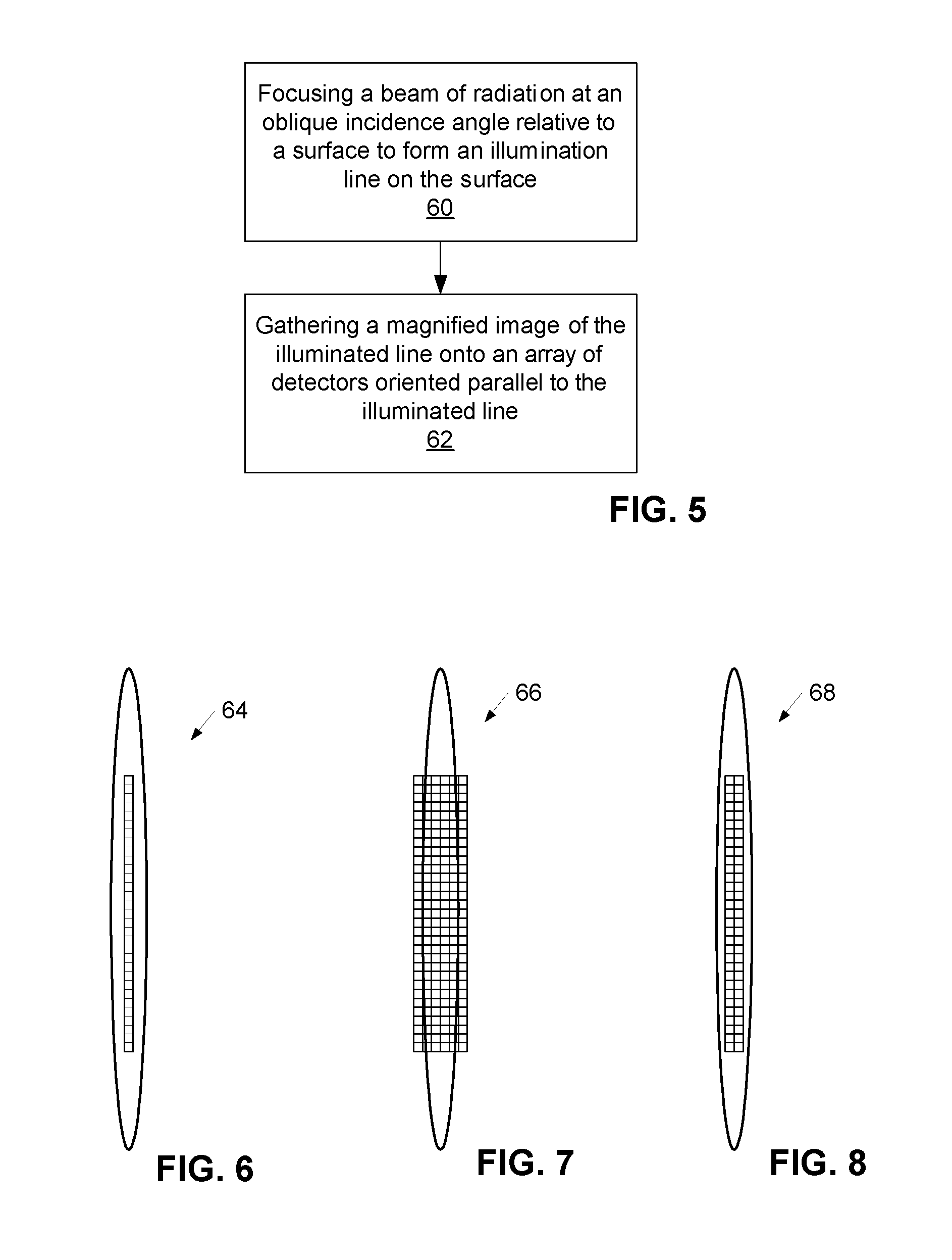
[0024]Turning now to the drawings, exemplary embodiments of surface inspection systems and methods for imaging illuminated lines on surfaces using such systems are illustrated. In particular, FIG. 1 depicts a perspective view of surface inspection apparatus 10 having illumination system 11 and collection system 21 for inspecting areas of surface 20. In addition, FIGS. 2-4 respectively illustrate partial cross-sectional views of surface inspection systems 30, 40 and 50 having alternative configurations of collections systems as compared to apparatus 10. Furthermore, FIG. 5 illustrates a flowchart of a method for imaging areas of surfaces using the systems described in reference to FIGS. 1-4 as well as the systems described herein having variations to the systems depicted in FIGS. 1-4.

[0025]In general, the surface inspection systems described herein may be used to inspect a surface of any object. For example, the systems may be used to inspect rough films, patterned or unpatterned sem...


PUM


Abstract

A surface inspection apparatus and a method are provided which include an illumination system configured to focus a beam of radiation at a non-orthogonal incidence angle to form an illumination line on a surface substantially in a plane of incidence of the focused beam. The apparatus and method further include a collection system configured to image the illumination line onto an array of detectors oriented parallel to the illumination line. The collection system includes an imaging lens for collecting light scattered from the illumination line, a focusing lens for focusing the collected light, and the array of detectors, each configured to detect a corresponding portion of the illumination line. The collection system may be configured to image the illumination line such that the width of the imaged illumination line on the array of detectors is larger than the pixel size of the detectors along the same direction.

Description

BACKGROUND OF THE INVENTION[0001]1. Field of the Invention[0002]This invention generally relates to surface inspection systems and, more specifically, to an apparatus and method for inspecting a surface using line-illumination imaging techniques.[0003]2. Description of the Related Art[0004]The need to inspect surfaces of objects is prevalent in many situations and for a variety of purposes. For example, it is generally advantageous to inspect surfaces of semiconductor wafers for defects and / or examination of features. Some surface inspection tools employ systems for illuminating a region of a surface, such as a semiconductor wafer. In some systems, the illumination beam may be specifically configured to illuminate a line-shaped region of the surface to be inspected. In such cases, the surface inspection system may further include systems, such as charge coupled devices, for imaging the illuminated line using light sensitive elements (referred to herein as detector elements) to colle...

Claims


Application Information

Patent Timeline
IPC IPC(8): G01N21/00
CPCG01N21/8806G01N21/9501G01N2021/8822G01N2021/9513G01N2021/95676
Inventor LEONG, JENN-KUENZHAO, GUOHENGVAEZ-IRAVANI, MEHDI
Owner KLA TENCOR TECH CORP
Why Eureka
Try Eureka