

Spectroscopic chemical analysis methods and apparatus
a spectroscopic and chemical analysis technology, applied in the field of noncontact spectroscopic methods and apparatuses, can solve the problems of difficult to ensure stoichiometrical reactions, inconvenient operation, and large majority of chemicals that do not absorb strongly, and achieve the effect of reducing weigh
- Summary
- Abstract
- Description
- Claims
- Application Information
AI Technical Summary
Benefits of technology
Problems solved by technology
Method used
Image

Examples
Embodiment Construction
Deep UV Radiation Production Methods and Sources
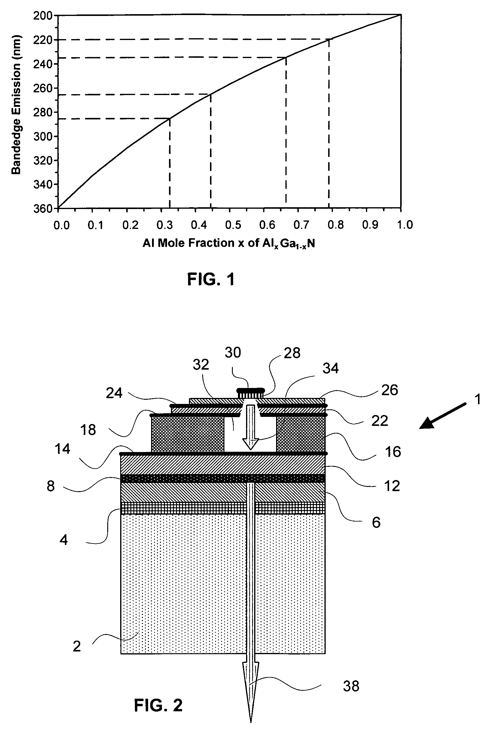
[0119]To avoid the difficulties, set forth above, related to producing deep UV semiconductor sources, Applicants have developed a pumping approach that uses ballistic electron beam injection directly into the active region of a wide band gap semiconductor material. One element that distinguishes some embodiments of the invention from the teachings about electron beam pumping noted above is that none of the publications discuss, describe, or suggest the use of wide bandgap semiconductor materials (i.e. semiconductor materials having a band gap greater than 3.5 eV, corresponding to wavelengths less than 400 nm, more preferably greater than 4.15 eV, corresponding to wavelengths less than 300 nm, and most preferably greater than 4.97 eV, corresponding to wavelengths less than 250 nm). Furthermore these references fail to teach the use of a Group III nitride semiconductor material systems, such as an AlGaN alloy, for producing laser output ...
PUM
 Abstract
Description
Claims
Application Information