
Stabilized non-lethal projectile systems

a projectile system and non-lethal technology, applied in the field of non-lethal projectile systems, can solve the problems of increasing the risk that a criminal will be surrounded or in close proximity to innocent persons by officers, not killing the bystander, and achieving the effect of maximizing its effectiveness

Inactive Publication Date: 2009-05-05
PEPPERBALL TECH
View PDF125 Cites 51 Cited by
  • Summary
  • Abstract
  • Description
  • Claims
  • Application Information

AI Technical Summary

Benefits of technology

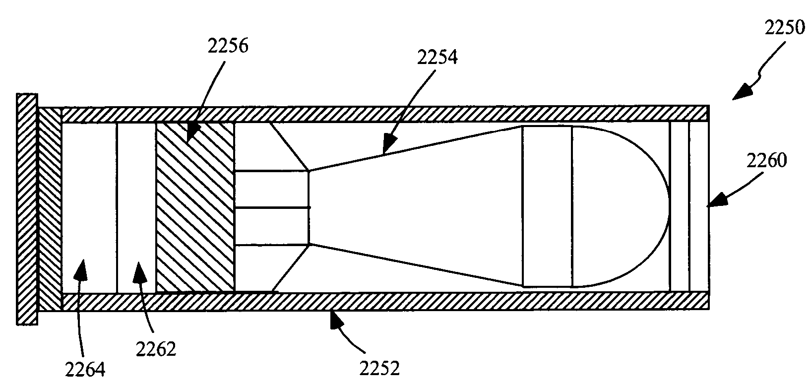
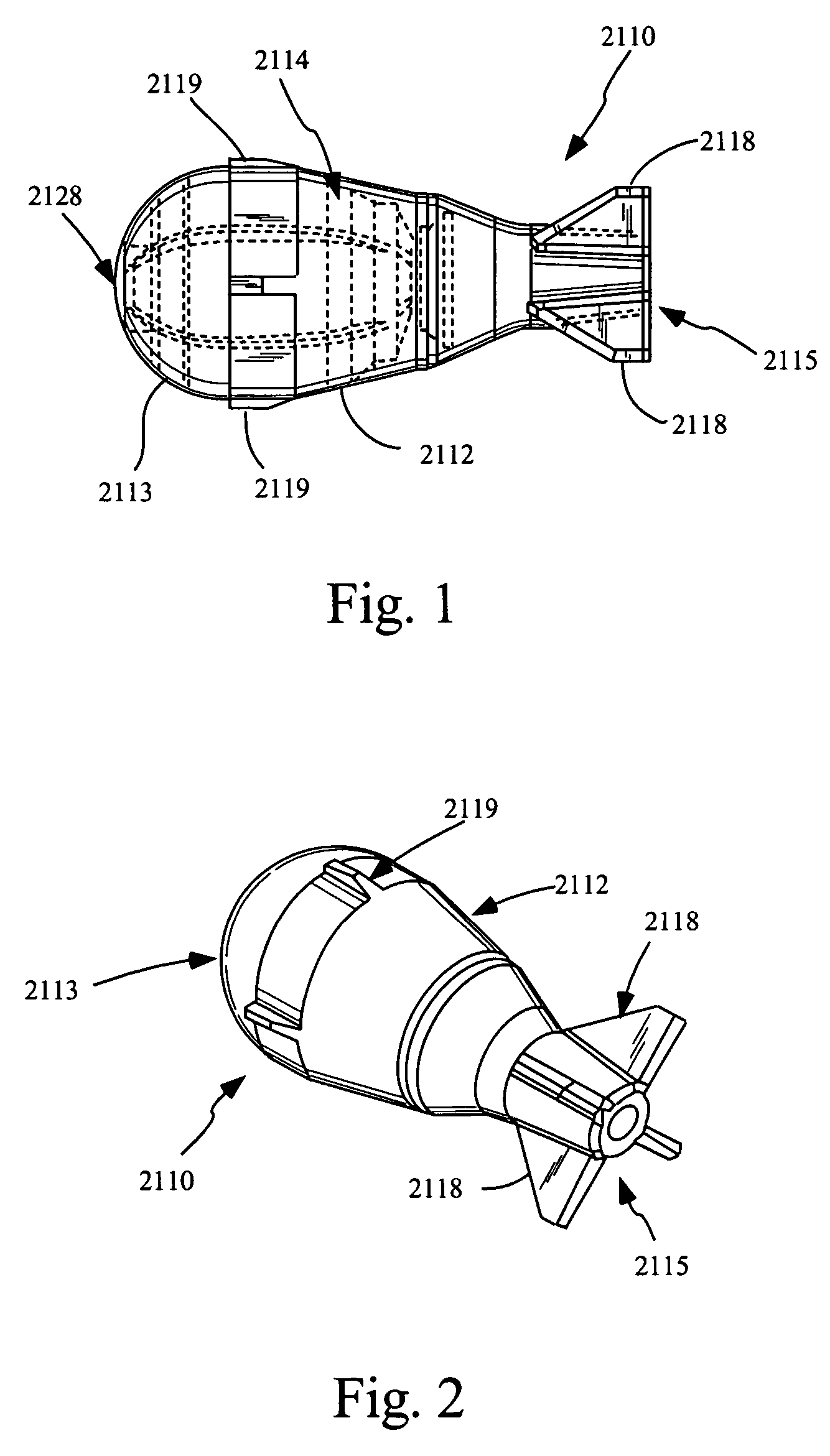
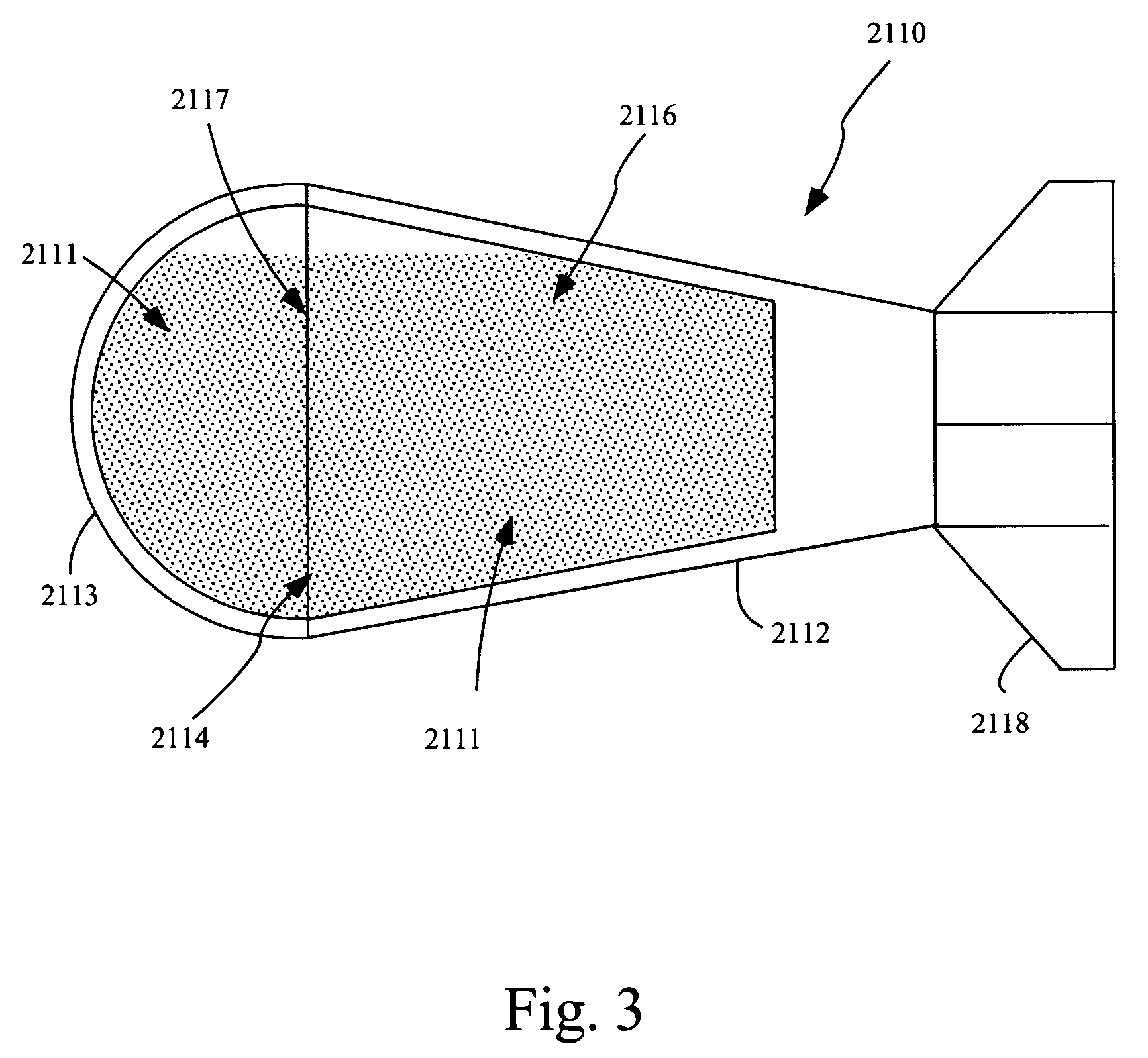
"The present invention provides a non-lethal or less-than-lethal projectile system for delivering a substance to a target, especially a living target, such as a human or animal target. The system has a kinetic impact against the target at a first location on or near the target and optimizes the dispersement of the substance on and / or about the target at a second location. The system includes a projectile with a hollow portion containing the inhibiting substance and stabilizing fins. The projectile system can also include a cartridge for launching the projectile and a frangible portion housing at least a portion of a dispersible payload. The system can also include means for spin stabilizing and a flexible nose section. The technical effects of the invention include improved effectiveness, better target impact, and optimized substance dispersal."

Problems solved by technology

As populations increase, the risk that a criminal will be surrounded by or in close proximity to innocent persons when officers are trying to subdue him / her also increases.
Whereas non-permanently injuring an innocent bystander, while subduing a suspected criminal, is acceptable, killing the bystander is not.
Disadvantageously, the projectiles described by Fogelgren, particularly those projectiles described that would be suitable for delivering loads such as tear gas or dye, are complicated and expensive to manufacture.
In addition, such embodiment requires complicated and tedious methods to manufacture components such as a microminiature ball valve (through which the portion of the pressurized gas enters the rear chamber upon firing), wax sealer within each of the plurality of apertures and a holding pin that must fall away from the projectile in flight.
The embodiment employing the breakable glass vial is also complicated to manufacture, because it also employs a holding pin that must fall away during the flight of the projectile and employs numerous structures that must be precisely fitted together to allow them to separate during firing and in flight.
This can be particularly problematic, for example, when the Fogelgren device is being used by a police officer in pursuit of a fleeing criminal (or when used by a police officer threatened by a suspected criminal).
The Kotsiopoulos, et al. disclosure includes a passing reference to the use of such a paint ball for delivering dyes, smoke or tear gas to a target, however, provides no mechanism for dispersing an inhibiting load upon explosion of the projectile, which is important for a non-lethal inhibiting projectile to be effective.
Thus, even if one skilled in the art were to act upon the passing reference to using tear gas in the Kotsiopoulos, et al. patent, to using tear gas, the present inventors believe that such a device would be generally ineffective because the tear gas would not be dispersed to the target's face, where it needs to be to be effective.
Furthermore, as Kotsiopoulos, et al. is an unpressurized projectile, the amount of tear gas delivered would necessarily be limited to an unpressurized volume having dimensions of a paint ball.
Even if this amount of tear gas were delivered to a target's face, it is unlikely that this amount of tear gas would be sufficiently effective to impair the target in a useful way.
While each of the devices described by these patents attempts to provide a projectile that may be used to stop or slow a living target without causing lethal injury, all of the devices have proven to be less than ideal.
They are complicated and expensive to manufacture, and they are variously difficult to use and unreliably effective.
As a result of these problems and others, there is no widely commercially accepted non-lethal projectile in use by law enforcement or military personnel today that delivers an inhibiting substance to a target.

Method used


Image

  • Stabilized non-lethal projectile systems
  • Stabilized non-lethal projectile systems
  • Stabilized non-lethal projectile systems

Examples


Embodiment Construction

[0059]The following description of the presently contemplated best mode of practicing the invention is not to be taken in a limiting sense, but is made merely for the purpose of describing the general principles of the invention. The scope of the invention should be determined with reference to the claims.

[0060]As used herein, the term “projectile system” or “projectile” or “non-lethal projectile” refers generally to the entire projectile apparatus of the various embodiments of the present invention that travels to the target. For example, in all embodiments contemplated herein, the projectile system or projectile at least includes a projectile body that contains a substance for delivery to the target. For example, this projectile body may be embodied as a capsule having a hollow volume within that contains the substance. The terms “capsule”, “casing” and “shell” are used interchangeably herein to refer to an embodiment of the projectile body as being a container portion of the proj...


PUM


Abstract

Projectiles and projectile systems are provided herein employing an inhibiting and / or marking substance for impairing / marking a living target. In some embodiments, the systems include a first part being non-spherical and having an exterior, a plurality of stabilizing fins secured with the exterior of at the first part, and a second part have a hollow portion containing an inhibiting substance, wherein the second part is sealed with the first part to seal the inhibiting substance within at least the hollow portion. The first part can similarly have a hollow portion such that a volume is defined by the hollow portion of the first part and the hollow portion of the second part, wherein the inhibiting substance is contained within the volume. The fins can be angled to provide spin stabilizing.

Description

[0001]This application claims the benefit of U.S. Provisional Application No. 60 / 446,657, filed Feb. 10, 2003, incorporated herein by reference.FIELD OF THE INVENTION[0002]The present invention relates to a non-lethal projectile system and, more particularly to non-lethal projectiles that deliver an inhibiting and / or marking substance to a target, especially a living target.BACKGROUND OF THE INVENTION[0003]Steadily rising crime rates have led to an increased need for technologically enhanced crime devices. There is particularly a need for non-lethal devices that are capable of at least temporarily incapacitating, slowing or inhibiting a suspected criminal and / or marking such individuals for later identification. As populations increase, the risk that a criminal will be surrounded by or in close proximity to innocent persons when officers are trying to subdue him / her also increases. Whereas non-permanently injuring an innocent bystander, while subduing a suspected criminal, is accept...

Claims


Application Information

Patent Timeline
Patent Type & Authority Patents(United States)
IPC IPC(8): F42B8/00F42BF42B7/08F42B7/10F42B12/40F42B12/46F42B12/50F42B14/06
CPCF42B7/08F42B7/10F42B12/40F42B12/46F42B12/50
Inventor VASEL, EDWARD J.FUZAK, COREY A.
Owner PEPPERBALL TECH
Learn More