Apparatus to facilitate the holding of large bottles without integral handles

a bottle and accessory technology, applied in the field of reusable bottle holders, can solve the problems of bottle becoming easily deformable, increasing the difficulty of holding, and drawbacks of consumer handling, and achieve the effects of simple design, light weight and convenient us

Inactive Publication Date: 2009-05-05
SHASKEY SR MARK S
View PDF13 Cites 46 Cited by
  • Summary
  • Abstract
  • Description
  • Claims
  • Application Information

AI Technical Summary

Benefits of technology

[0015]Still another object of the present invention is to provide an improved bottle holding apparatus that is not subject to material fatigue or failure.
[0016]It is another object of the present invention to provide an improved bottle holding apparatus that does not contact the bottle along its most flexible, or deformable, central section.
[0017]It is another object of the present invention to provide a bottle holding device that does not block the view of the user as to the contents of the bottle contained within.
[0018]An additional object of the present invention is to provide an improved bottle holding apparatus that is simple in design, light in weight, easy to use, and relatively inexpensive to produce.
[0019]These and other objects are accomplished by a bottle holding apparatus comprising two, short, cylindrical sections, two or more struts fixedly connected between the two cylindrical sections, a handle fixedly attached to one of the struts, and one or more support ribs each fixedly attached to others of the struts. The bottle holding apparatus of the present invention provides a means for any user to reliably grasp any large, “handle-less” bottle, without causing any inappropriate deformation of the plastic, while dispensing its contents. The present invention is fabricated of strong, lightweight, metallic and / or plastic materials, such as aluminum or PVC, to provide the durability required by the nature of its usage. The present invention's design is simple and scalable (i.e. it may vary in size to fit various container dimensions / volumes), and can be economically manufactured and sold.
[0020]In use, the base of a large, “handle-less” bottle is inserted first through one cylindrical section and then into the second cylindrical section until it comes to rest against an end cap. The user may then remove the cap from the bottle and confidently pick up the bottle and bottle holding apparatus, via its handle, to dispense any amount of the liquid held therein. The configuration of the present invention positions the two cylindrical sections proximate the shoulder and base of the bottle. This minimizes the potential for inappropriate bottle deformation during dispensing because the structural rigidity of the bottle is greatest near its shoulder and base.

Problems solved by technology

Although these types of bottles permit a cost effective means for bottling soft drink beverages, there are drawbacks associated with their handling by consumers.
Unfortunately, as the contents of a bottle are emptied and replaced by air, particularly when the popular 2-liter bottle is involved, the bottle becomes easily deformable, thus increasing the challenge of holding on to it.
In fact, this deformation may increase to such a degree that the bottle slips from the grasp of the consumer, causing the spilling of the remainder of its contents along with other inconveniences and / or safety hazards.
Unfortunately, repeated use of this device can result in material fatigue, and eventually failure, either along the hinged edge of the plates or at the point(s) of cooperative engagement between the pin(s) and the ring opening(s).
Failure of the material along the hinged edge would result in the complete separation of the plates while failure of the material at the point(s) of cooperative engagement would result in the inability to hold the device closed around a bottle.
Either circumstance renders the device useless.
Unfortunately, in use, the Escalante and Henline apparatus can exert inappropriate forces along the central section of the bottle—the section of the bottle that is the most flexible, or deformable.
Inappropriate forces exerted on the mid-section of the bottle can cause the contents of the bottle to unexpectedly gush out of the neck opening resulting in unnecessary spillage.

Method used


Image

  • Apparatus to facilitate the holding of large bottles without integral handles
  • Apparatus to facilitate the holding of large bottles without integral handles
  • Apparatus to facilitate the holding of large bottles without integral handles

Examples


Embodiment Construction

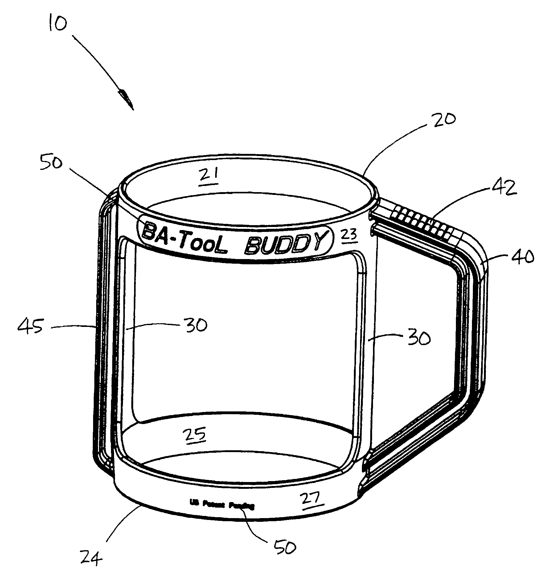
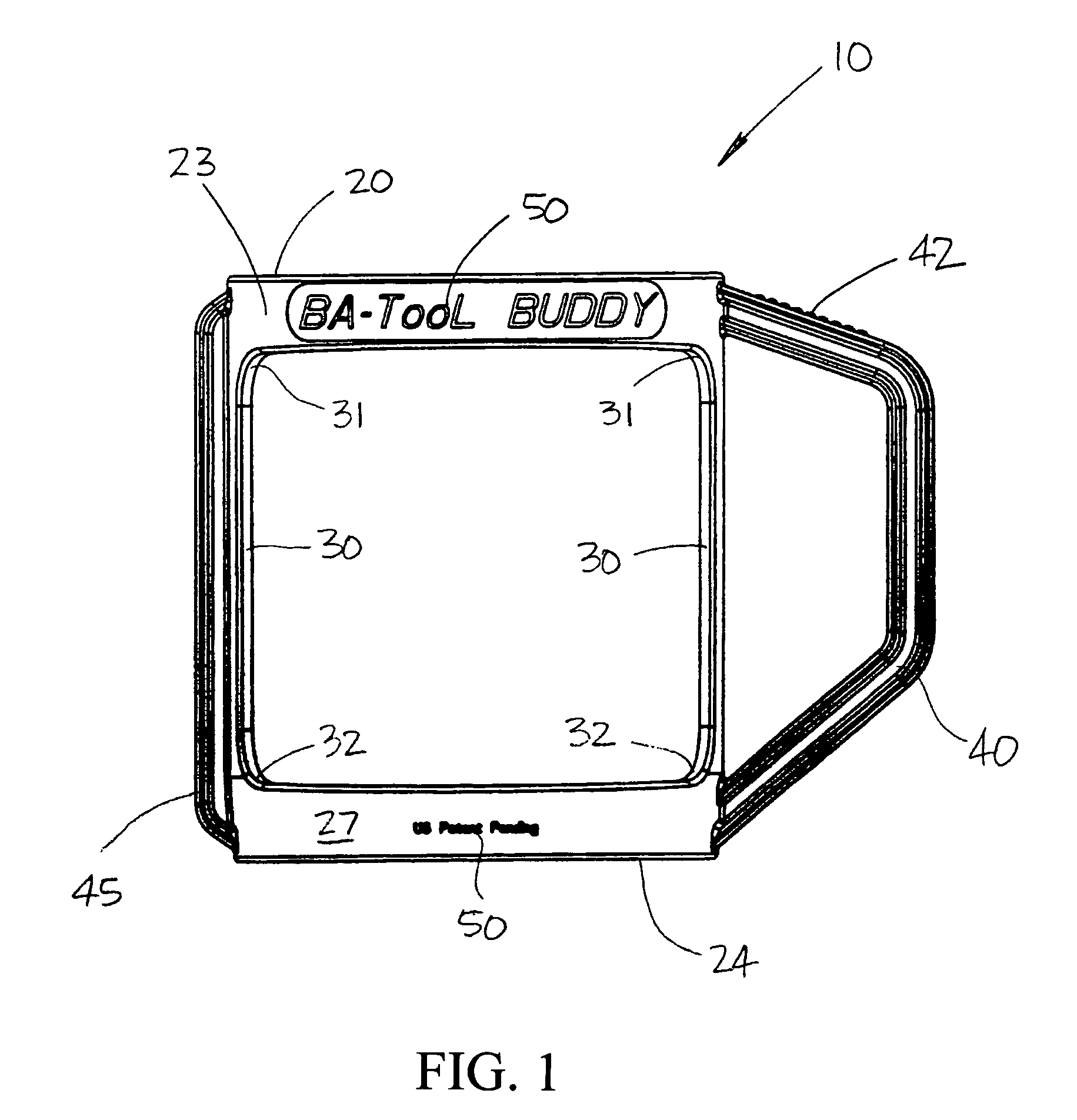
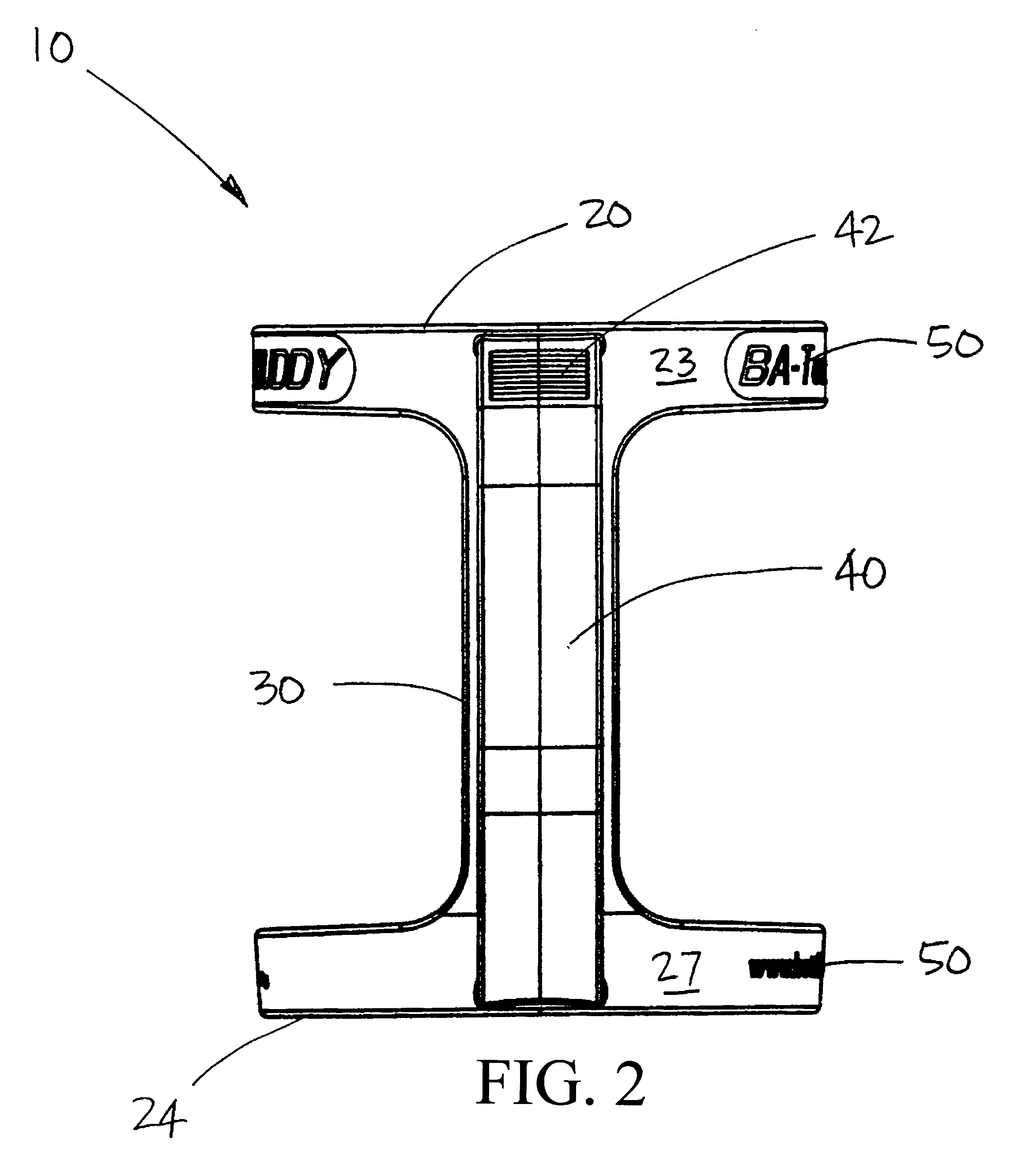
[0025]FIGS. 1-3 are, respectively, side, front, and isometric views of an improved bottle holding device 10 according to a first embodiment of the present invention. The first embodiment of the present invention generally comprises cylindrical sections 20, 24, two or more struts 30, a handle 40, and one or more support ribs 45.

[0026]The short, cylindrical sections 20, 24 are preferably fabricated of a lightweight metallic or plastic material. The inner surfaces 21, 25, respectively, of the cylindrical sections 20, 24 may be textured to provide means for releasably locking a bottle (not shown in the Figures) within the bottle holding apparatus 10. Additionally, cylindrical section 24 may be formed with a slight inward taper. The “friction fit” between the textured surfaces 21, 25 and the outer surface of the bottle, in combination with the slight inward taper of section 24, maintain the bottle within the holding apparatus 10 during any liquid dispensing cycle. The outer surfaces 23, ...


PUM


Abstract

Disclosed herein is a bottle holding apparatus comprising two, short, cylindrical sections, two or more struts fixedly connected between the two cylindrical sections, and a handle and support rib fixedly attached to two of the struts. The bottle holding apparatus of the present invention provides a means for any user to reliably grasp any large, “handle-less” bottle, without causing any inappropriate deformation of the plastic, while dispensing its contents. The present invention's design is simple and scalable, and can be economically manufactured and sold.

Description

CROSS-REFERENCE TO RELATED APPLICATION(S)[0001]The present application derives priority from U.S. Provisional Patent Application No. 60 / 413,976, filed Sep. 26, 2002.BACKGROUND OF THE INVENTION[0002]1. Field of the Invention[0003]The present invention relates to reusable holders for fluid containers and, more particularly, to a reusable bottle holder primarily designed for conventional, large soft drink bottles that do not possess integral handles.[0004]2. Description of the Background[0005]The marketing of soft drink beverages in large, plastic bottles (e.g. 2-liter, 3-liter), that are not equipped with integral handles, is commonplace. Bottles of this type are typically manufactured of relatively flexible plastics such as polyethylene teraphthalate (PET). Although these types of bottles permit a cost effective means for bottling soft drink beverages, there are drawbacks associated with their handling by consumers. Unfortunately, as the contents of a bottle are emptied and replaced ...

Claims


Application Information

Patent Timeline
Patent Type & Authority Patents(United States)
IPC IPC(8): B65D23/10
CPCB65D23/106
Inventor SHASKEY, SR., MARK S.
Owner SHASKEY SR MARK S
Why Eureka
Try Eureka