Stator turbine vane with improved cooling

a technology of turbines and turbine blades, which is applied in the direction of stators, machines/engines, liquid fuel engines, etc., can solve the problems of limiting the life of the turbine blades, affecting the operation of the turbine blade, and reducing the efficiency of the cooling of the airfoil, so as to reduce the radial stress acting on the turbine blades and mitigate the drawbacks

Active Publication Date: 2009-05-05
SN DETUDE & DE CONSTR DE MOTEURS DAVIATION S N E C M A
View PDF8 Cites 14 Cited by
  • Summary
  • Abstract
  • Description
  • Claims
  • Application Information

AI Technical Summary

Benefits of technology

[0008]The invention thus seeks to mitigate the drawbacks associated with these large variations in temperature gradient by proposing a turbomachine stator vane cooled by an open liner, in which the radial stresses acting on the vane are considerably reduced. The invention also relates to an entire turbomachine turbine fitted with such stator vanes cooled by open liners.
[0009]To this end, the invention provides a turbomachine stator vane having a leading edge, a trailing edge, and pressure side and suction side faces, and including a perforated open liner defining an annular cavity between an outside wall of the liner and an inside wall of the vane, an air admission opening for feeding cooling air to the inside of the liner, and an air exhaust opening for exhausting a fraction of this cooling air out from the vane, the liner being secured to the vane at one end and being free at another end to slide along an inside edge of the vane under the effects of relative thermal expansion between the liner and the inside wall of the vane, wherein said open liner includes a plurality of holes distributed over only two determined zones of said liner, a first series of holes being disposed facing the holes being disposed facing the inside wall of the trailing edge, the holes through the liner in the second series of holes also being disposed in such a manner as to avoid any impact against the bridges of the vane.
[0010]As a result, by contributing to cooling at the leading and trailing edges of the vane and by limiting impacts against the bridges, local temperature gradients are greatly reduced as are the axial stress levels on the airfoil.

Problems solved by technology

These turbine vanes are subjected to the very high temperatures of the combustion gas which can reach values well above those that the vanes in direct contact with the gas can withstand without damage, which has the consequence of limiting their lifetime.
Nevertheless, the fact that the air is calibrated by the holes through the liner and indirectly by the leakage section leads to cooling of the airfoil that is less efficient.
In addition, large variations appear locally in the temperature gradient over the wall of the vane, in particular in the vicinity of the leading edge, and these variations lead to radial stresses which, under extreme conditions of use, turn out to be harmful to the operation of the vane.

Method used


Image

  • Stator turbine vane with improved cooling
  • Stator turbine vane with improved cooling
  • Stator turbine vane with improved cooling

Examples


Embodiment Construction

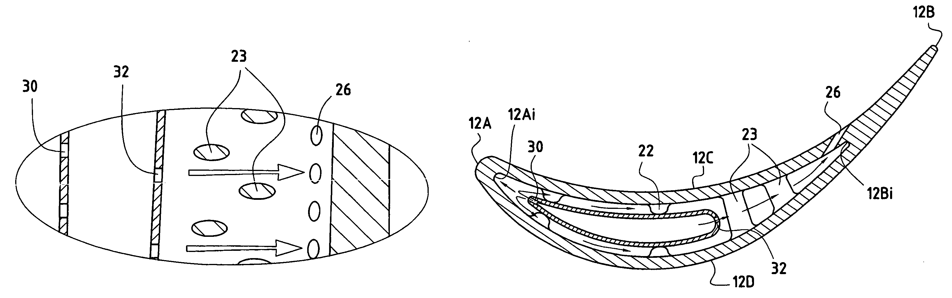
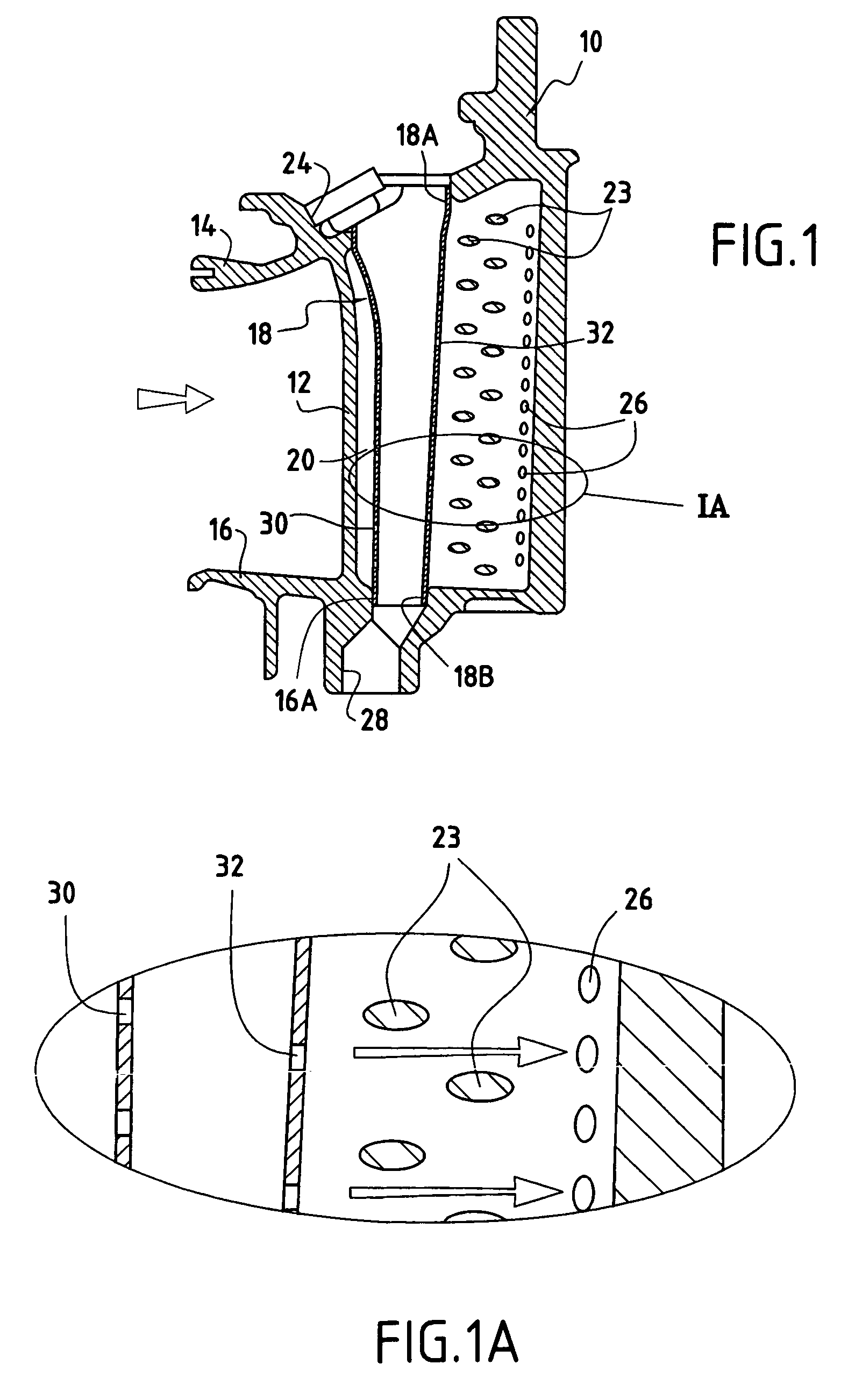
[0019]FIGS. 1 and 2 show a cooled vane 10, e.g. a stator vane for a turbomachine turbine nozzle in accordance with the present invention. The vane comprises a hollow airfoil 12 mounted between an outer platform 14 and an inner platform 16 and it is secured to a casing (not shown) of the turbine via the outer platform which defines an outer wall for the stream of combustion gas flowing through the turbine, the inner wall of the flowing stream being defined by the inner platform of the vane.

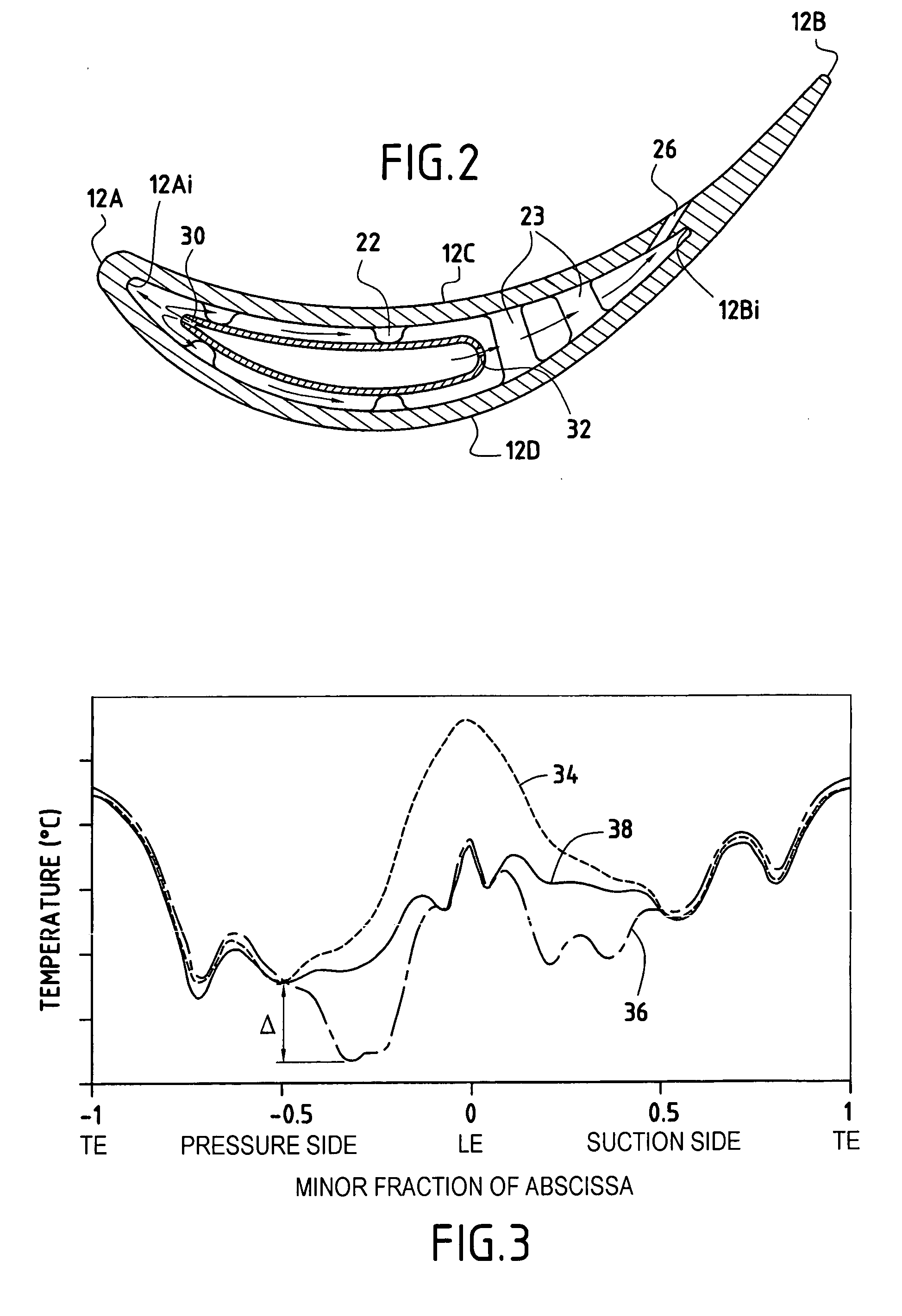
[0020]Conventionally, with respect to the direction of flow of combustion gas as represented by an arrow in FIG. 1, the vane is said to have a leading edge 12A and a trailing edge 12B, together with a pressure side face 12C and a suction side face 12D.

[0021]Such a stator vane is subjected to the very high temperatures of combustion gas and therefore needs to be cooled. For this purpose, and in conventional manner, the vane 10 includes at least one perforated open liner 18 fed with cooling air via o...


PUM


Abstract

A turbomachine stator vane having a leading edge, a trailing edge, and pressure side and suction side faces, a first and a second series of a plurality of holes, calibrated emission holes, and a perforated open liner defining an annular cavity between an outside wall of the liner and an inside wall of the vane, an air opening for feeding cooling air to the inside of the liner, and an air exhaust opening for exhausting cooling air from the vane, the liner being secured to the vane at one end and being free at another end to slide along an inside edge of the vane under the effects of relative thermal expansion between the liner and the inside wall of the vane. The holes through the liner in the second series of holes are disposed to avoid any impact of the cooling air against the bridges of the vane.

Description

FIELD OF THE INVENTION[0001]The present invention relates to the general field of turbine vanes for turbo-machinery, and more particularly to stator turbine vanes fitted with integrated cooling circuits.PRIOR ART[0002]In known manner, a turbomachine has a combustion chamber in which air and fuel are mixed prior to being burnt therein. The gas coming from such combustion flows downstream from the combustion chamber and then feeds a high pressure turbine, and then a low pressure turbine. Each turbine has one or more stator-vane rows (also known as nozzles) alternating with one or more moving-blade rows (also known as rotor disks), the rows being spaced circumferentially all around the rotor of the turbine. These turbine vanes are subjected to the very high temperatures of the combustion gas which can reach values well above those that the vanes in direct contact with the gas can withstand without damage, which has the consequence of limiting their lifetime.[0003]In order to solve this...

Claims


Application Information

Patent Timeline
Patent Type & Authority Patents(United States)
IPC IPC(8): F01D25/12F01D5/08F01D5/18F01D9/02
CPCF01D5/189F01D9/02Y02T50/676Y02T50/60
Inventor GUIMBARD, JEAN-MICHELPABION, PHILIPPESCHWARTZ, ERIC
Owner SN DETUDE & DE CONSTR DE MOTEURS DAVIATION S N E C M A
Why Eureka
Try Eureka