
Stent with geometry determinated functionality and method of making the same

a technology of stents and geometry, applied in the field of medical devices, can solve the problems of unsuitable stent technology, unfavorable stent production, and inconvenient installation, and achieve the effects of reducing infection, avoiding undesirable effects, and reducing the number of stents

Inactive Publication Date: 2009-05-05
MERIT MEDICAL SYST INC
View PDF438 Cites 52 Cited by
  • Summary
  • Abstract
  • Description
  • Claims
  • Application Information

AI Technical Summary

Benefits of technology

The present invention provides a stent that combines the benefits of silicone and metal stents while eliminating their drawbacks. The stent is easy to install, removable, and can be used for both permanent and temporary use. It maintains its shape when compressed and can be indicated for the treatment of benign and malignant disease. The stent is economical, suitable for routine use, and has minimal migration, tissue granulation, foreshorting, and mucociliary clearance issues. It has a superior internal to external diameter ratio, radial force with dynamic expansion, and can be used in pediatric and adult patients. The stent has different hardness / softness regions to provide additional patient comfort and resistance to radial forces. It also has novel interstice configurations for flexibility, durability, and proper installation. The stent has plurality of apertures at the termini for easy removal.

Problems solved by technology

Vascular as well as not vascular stenting has evolved significantly; unfortunately there remain significant limitations with respect to the technology for producing stents suitable to various portions of a patient's anatomy.
Unfortunately, braided stents are vulnerable to premature obsolescence.
Moreover, providing multiple material types in a single stent may lead to inconsistent characteristics along the surface area of the stent.
This is particularly undesirable when the stent is to be placed in vascular or nonvascular lumens that have been occluded for one reason or another.

Method used


Image

  • Stent with geometry determinated functionality and method of making the same
  • Stent with geometry determinated functionality and method of making the same
  • Stent with geometry determinated functionality and method of making the same

Examples


Embodiment Construction

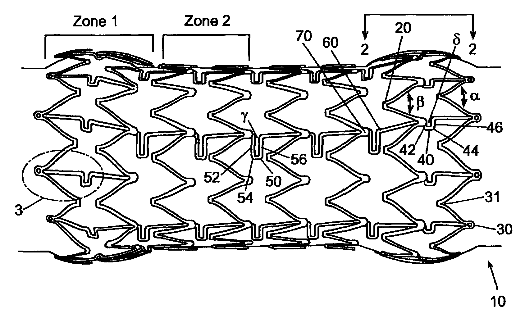
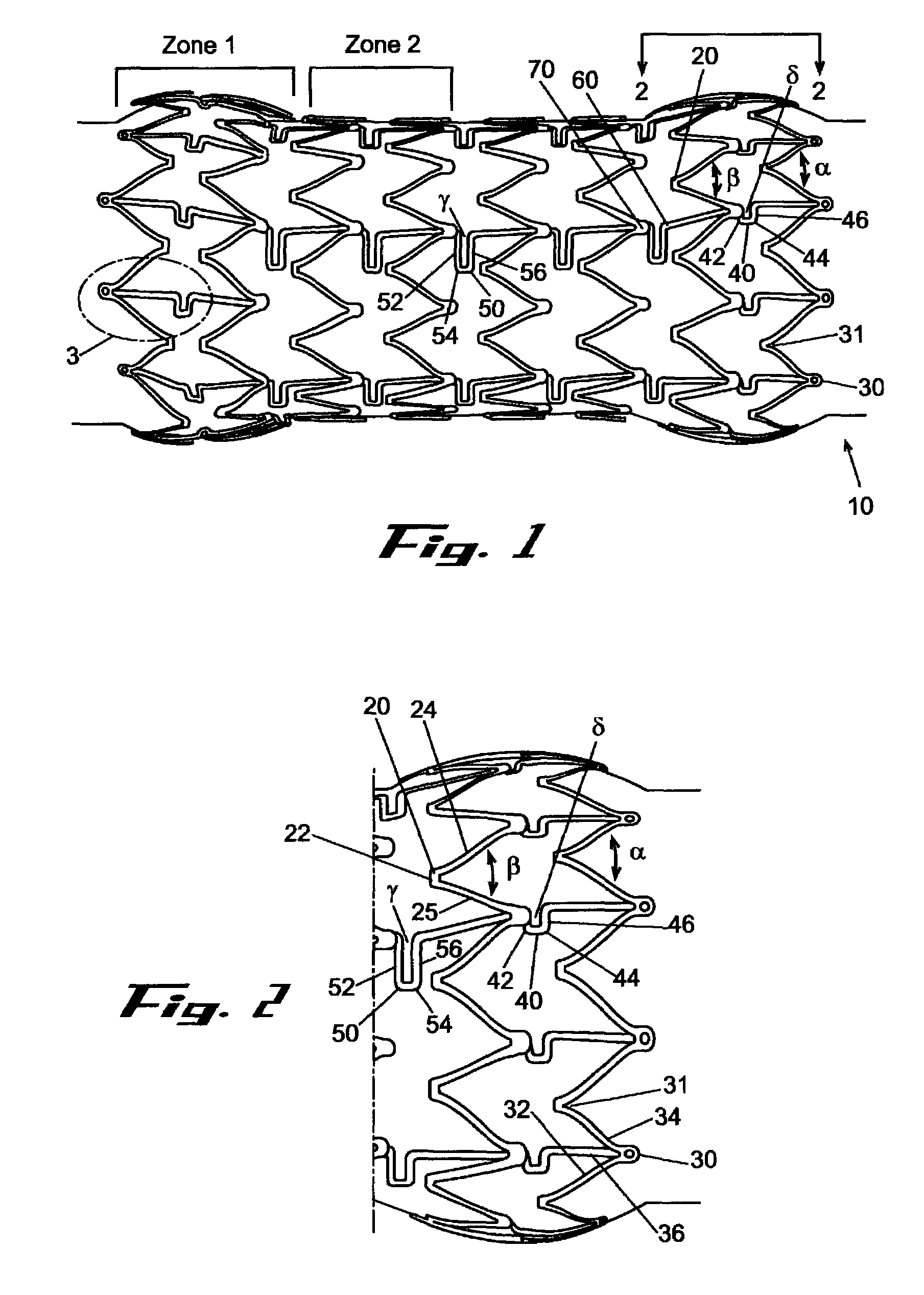
[0004]It is a principal purpose of the present invention to provide a stent, in accordance with an exemplary embodiment of the present invention, which combines many of the excellent characteristics of both silicone and metal stents while eliminating the undesirable ones. In particular, it is an objective of a preferred embodiment in accordance with the present invention to provide a stent that is easily installed, yet in alternative embodiments, removable. Moreover the stent in accordance with this embodiment of the present invention would not cause material infections and may be capable of reducing infection. Therefore, a principal objective of a preferred embodiment in accordance with the present invention is to provide a prosthesis that is suitable for both permanent and temporary use while being easy to insert, reposition and remove.

[0005]A principal objective of a preferred embodiment of the present invention is to provide a stent that may be stamped from preferably a single m...


PUM

PropertyMeasurementUnit
angleaaaaaaaaaa
anglesaaaaaaaaaa
obtuse anglesaaaaaaaaaa

Abstract

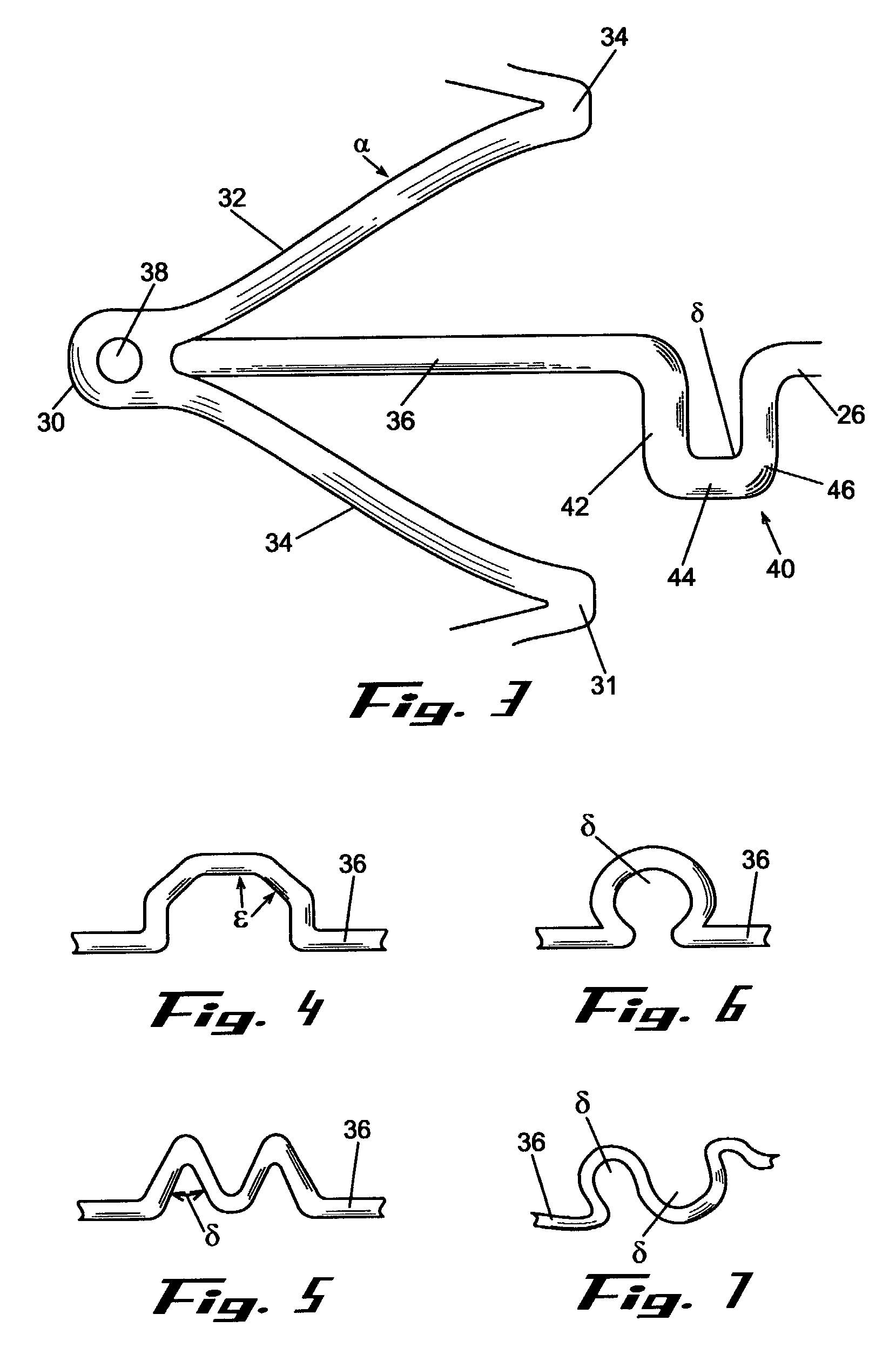
The present invention, in an exemplary embodiment, provides a stent, which combines many of the excellent characteristics of both silicone and metal stents while eliminating the undesirable ones. In particular, a principal objective in accordance with the present invention is to provide a family of stents where the relative hardness / softness of regions of the stent can differ from other regions of the stent to provide additional patient comfort and resistance to radial forces. An exemplary embodiment also provides a family of stents with novel interstice configurations that facilitate flexibility, durability and / or proper installation.

Description

FIELD OF INVENTION[0001]The present invention relates generally to medical devices directed to the prevention of luminal occlusion, and more particularly to stents and methods for making and utilizing these stents in the treatment of both benign and malignant conditions wherein the functionality of the stents is determined by geometrical variability of the scaffolding and concomitant interstices.BACKGROUND OF THE INVENTION[0002]Stents are devices that are inserted into a vessel or passage to keep the lumen open and prevent closure due to a stricture, external compression, or internal obstruction. In particular, stents are commonly used to keep blood vessels open in the coronary arteries and they are frequently inserted into the ureters to maintain drainage from the kidneys, the bile duct for pancreatic cancer or cholangiocarcinoma or the esophagus for strictures or cancer. Vascular as well as not vascular stenting has evolved significantly; unfortunately there remain significant lim...

Claims


Application Information

Patent Timeline
Patent Type & Authority Patents(United States)
IPC IPC(8): A61F2/06A61F2/00A61F2/90A61L31/08
CPCA61F2/91A61F2/915A61L31/08A61F2/07A61F2/856A61F2002/91533A61F2002/91575A61F2250/0018A61F2250/0051A61F2230/0013
Inventor MANGIARDI, ERIC K.REYNOLDS, JASON M
Owner MERIT MEDICAL SYST INC
Learn More