Connection node for a universal truss joint and double layer grid

a technology of connecting nodes and trusses, applied in the direction of joists, girders, buildings, etc., can solve the problems of difficult design and construction of contoured (free-form) footprints, more expensive design and fabrication processes, and difficult to produce flat double-layer grids. , to achieve the effect of simplifying the problem of attachment and simplifying the connection

Inactive Publication Date: 2009-05-12
GOSSAMER SPACE FRAMES
View PDF19 Cites 40 Cited by
  • Summary
  • Abstract
  • Description
  • Claims
  • Application Information

AI Technical Summary

Problems solved by technology

Ball-node systems are designed for the use of round cross-sections (pipes) in double-layer-grids and involve a more expensive design and fabrication process.
There are several disadvantages of the connection systems of the prior art when applied to double-layer grids as described with square cross-section framing elements.
First, these systems are restricted to square, double-layer-grids only.
Second, these systems can only produce flat double-layer grids.
Third, contoured (free-form) footprints are difficult to design and construct.
Fourth, vertical sidewall and / or end wall framing is difficult to design and construct.

Method used


Image

  • Connection node for a universal truss joint and double layer grid
  • Connection node for a universal truss joint and double layer grid
  • Connection node for a universal truss joint and double layer grid

Examples


Embodiment Construction

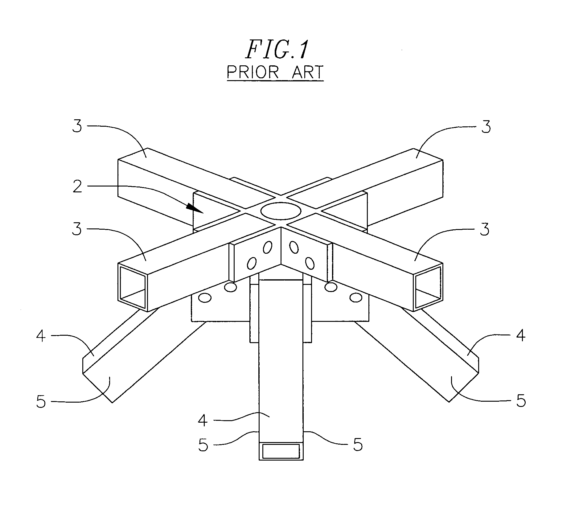
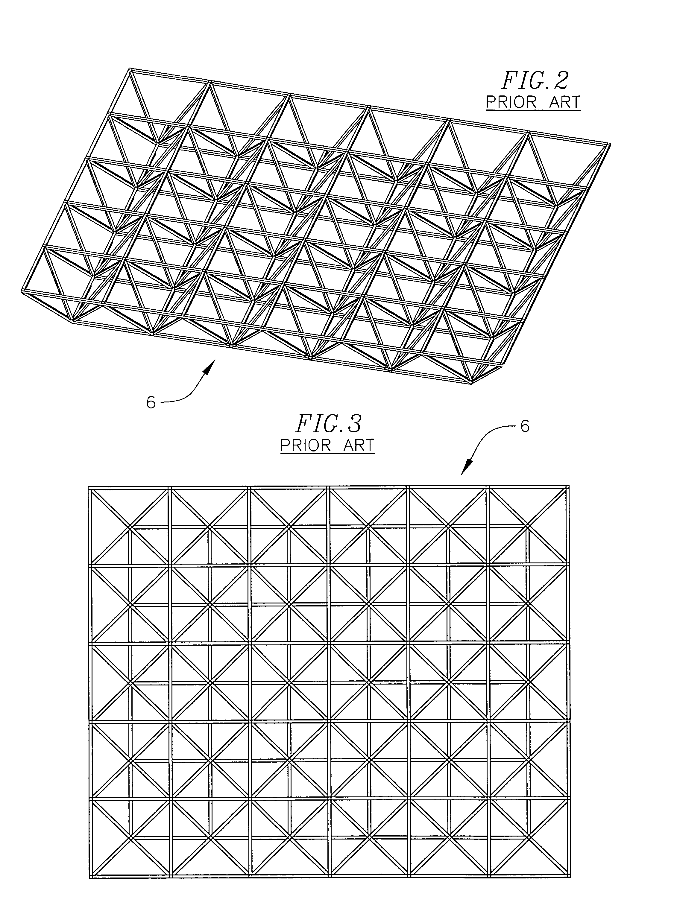
[0022]FIGS. 5 through 7 depict a simplified representation of prior art node connector joint 2 (see FIG. 1) and illustrate the existing convention for member orientation in conventional double-layer-grids. Wide-flanged (WF) members are shown for grid framing members 3, 4 in FIGS. 5-7 to help visualize strut member orientation. As seen in FIG. 5, the diagonal member in the foreground has the web oriented vertically as do the other diagonal members connected to that node connection joint. FIG. 6 shows the same joint 2 in a bottom view in which the intersections of the diagonal struts 4 trace a cruciform which indicates that the flat flange surfaces of the WF diagonals are in separate planes. FIG. 7 is a close-up of a joint from space frame 6 (see FIG. 4) which illustrates that the flanges of the strut 4 members are not parallel to the plane defined by the row of diagonals in each half-bay.

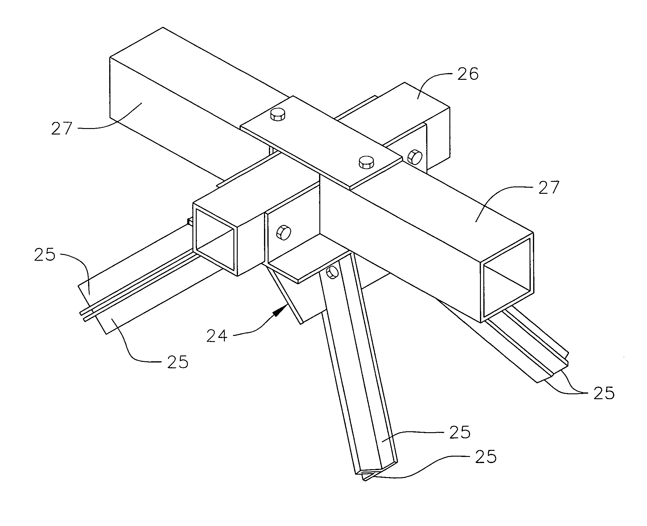
[0023]A simplified depiction of a DLGC joint 8 according to the present invention is shown in FIG...


PUM


Abstract

A connection node for a double layer grid or truss system has at least one diagonal flange receiving a pair of diagonal framing members having surfaces that lie in a single diagonal plane parallel to the flange(s). Use of co-planar diagonal members that can be at various diagonal angles or vertical, simplifies node connections and permits variations in bay spacing to produce interesting architectural effects and to provide greater member density where structural loads are greater.

Description

FIELD OF THE INVENTION[0001]The present invention relates to connections for joining linear, structural elements capable of carrying tension and compression loads that comprise double-layer-grid, three-dimensional trussed structures and braced planar truss systems. The most common application of such connections is in double-layer-grid space frames. Therefore, the connection hereof is named after the acronym for double-layer-grid—the DLG Connector (DLGC).BACKGROUND ART[0002]Current connections designed for double-layer-grids receive linear, structural elements that, most commonly, are either round or square in cross-section. In such grids, the places where plural linear elements are interconnected are known as “nodes”. FIG. 1 illustrates a conventional node connector 2 for square cross-section framing members 3, 4. Note that the adjacent diagonal strut members at 4 the connection reside in different planes. That is, the non-vertical surfaces 5 of each diagonal strut member 4 lie in ...

Claims


Application Information

Patent Timeline
Patent Type & Authority Patents(United States)
IPC IPC(8): E04B7/08
CPCE04B1/19E04B1/1903E04B2001/1933E04B2001/1936E04B2001/1975E04B2001/1984E04B2001/199E04C2003/0495
Inventor REYNOLDS, GLENN A.HACKBARTH, DEAN R.CURTIS, GARY N.
Owner GOSSAMER SPACE FRAMES
Why Eureka
Try Eureka