Saddle clamp having electrical bonding character

a saddle clamp and electrical bonding technology, applied in the direction of connection contact member materials, coupling device connections, applications, etc., can solve the problems of improper grounding of one or more cables, fuel line electrical charges, and increase assembly time, so as to reduce the need for external electrical contact wire connections, reduce complexity, and enhance electrical coupling and charge dissipation

Active Publication Date: 2013-12-10
ILLINOIS TOOL WORKS INC
View PDF12 Cites 24 Cited by
  • Summary
  • Abstract
  • Description
  • Claims
  • Application Information

AI Technical Summary

Benefits of technology

[0006]The present invention offers advantages and alternatives over the prior art by providing a saddle clamp which incorporates internal electrical bonding elements adapted to maintain electrical contact with a clamped tube structure without transferring structural load between the tube and the electrical bonding components. Electrical contact connections are thereby maintained without imparting sliding wear to the tubing and the need to use external electrical contact wire connections is reduced or eliminated. Accordingly, such an arrangement substantially reduces complexity while providing enhanced electrical coupling and charge dissipation.

Problems solved by technology

Thus, friction may cause electrical charges to build up on the fuel lines during use.
As will be appreciated, while this arrangement is quite effective in dissipating electrical charge, it requires a number of additional components and connections thereby increasing assembly time.
Moreover, since the conductive cables must be attached by a person, there is a possibility that human error may result in one or more of the cables being grounded improperly or not at all.
Further, even when all connections are properly made during initial installation, one or more cables may become disengaged during use or routine maintenance thereby reducing the efficiency of the electrical contact system.

Method used


Image

  • Saddle clamp having electrical bonding character
  • Saddle clamp having electrical bonding character
  • Saddle clamp having electrical bonding character

Examples


Embodiment Construction

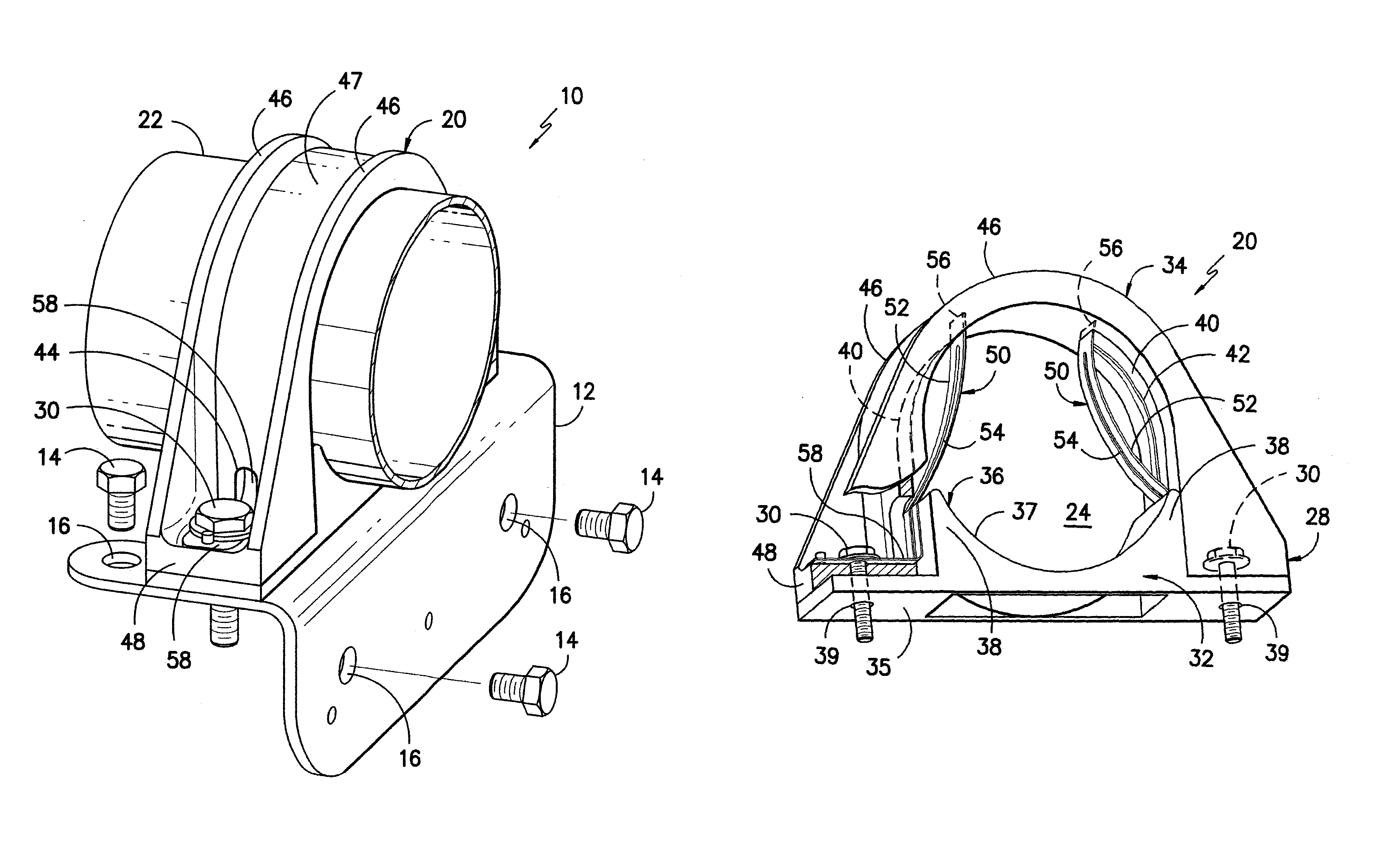
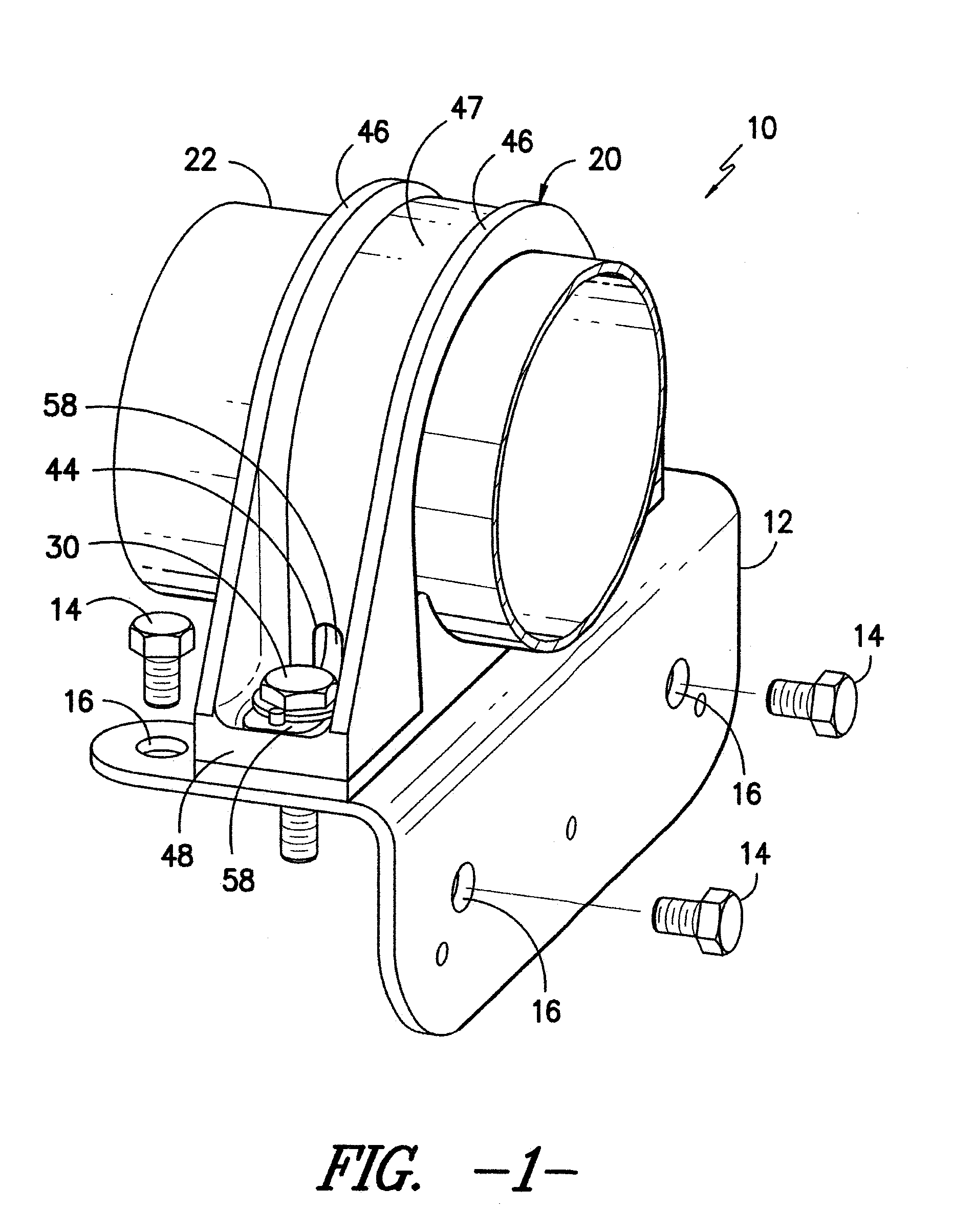
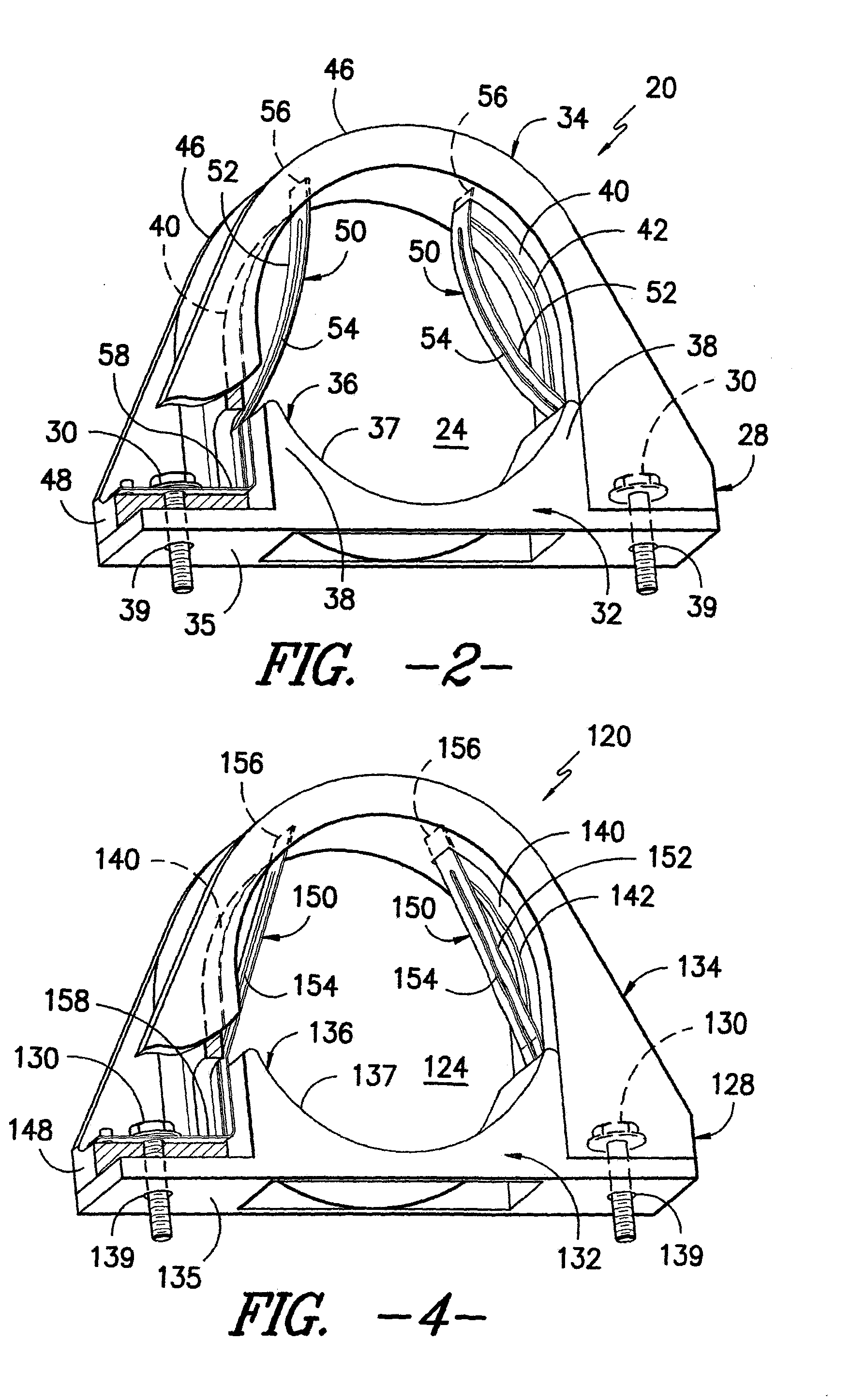
[0014]Exemplary embodiments of the invention will now be described in reference to the drawings, wherein like reference numerals designate like elements in the various views. Referring now to the drawings, in FIG. 1, an improved exemplary tube clamping system 10 is shown. As illustrated, the exemplary tube clamping system 10 incorporates a metal bracket 12 which may be attached to a portion of a metal support structure (not shown) by use of connection bolts 14 extending through attachment openings 16 in a manner as will be well known to those of skill in the art. By way of example only, the support structure may be a portion of an aircraft frame although the clamping system 10 may likewise be used in conjunction with virtually any support structure arrangement in numerous alternative environments of use. Without limitation, such alternative environments of use may include petrochemical plants, ground-based fuel storage depots, fuel tanker trucks and the like.

[0015]As shown, the exem...


PUM


Abstract

A saddle clamp which incorporates internal electrical bonding elements adapted to maintain electrical contact with a clamped tube structure without transferring structural load between the tube and the electrical bonding components. The saddle clamp includes an inner tube contacting surface having at least one surface groove. At least one electrical contact element extends between portions of the inner tube contacting surface. The electrical contact element includes tube contact segment disposed in opposing relation to a portion of the surface groove. The electrical contact element is electrically connected to the mounting bracket to transmit electrical charge from the tube.

Description

CROSS-REFERENCE TO RELATED APPLICATION[0001]This non-provisional application is national phase of PCT / US2010 / 054049 filed Oct. 26, 2010, and claims the benefit of, and priority from, U.S. Provisional Application 61 / 256,693 filed Oct. 30, 2009.TECHNICAL FIELD[0002]The present invention relates to clamping structures, and more particularly to a saddle clamp adapted to support metal piping or tubing such as a fuel tube or the like in an aircraft or other environment of use. More particularly, the present invention relates to a saddle clamp providing electrical contact between the clamped tubing and a metal support frame or other electrical contact structure.BACKGROUND OF THE INVENTION[0003]It is known to use plastic saddle clamps to hold piping or tubing in place. One environment of use for such saddle clamps is to support fuel lines or other tubing structures in an aircraft wing. In this environment the saddle clamp is required to accommodate flexing of the fuel line without significa...

Claims


Application Information

Patent Timeline
Patent Type & Authority Patents(United States)
IPC IPC(8): H01R4/66H01R13/648
CPCF16L3/00F16L3/1091H01R4/46H01R4/643B64D37/32
Inventor DOWNING, MARK L.
Owner ILLINOIS TOOL WORKS INC
Why Eureka
Try Eureka