Combustion chamber and a combustion chamber segment

a combustion chamber and combustion chamber technology, applied in continuous combustion chambers, combustion processes, lighting and heating apparatus, etc., can solve the problems of limited cooling effect of current gas turbine engine combustion chamber walls and high manufacturing costs of combustion chamber walls of current gas turbine engines

Active Publication Date: 2016-09-08
ROLLS ROYCE PLC
View PDF28 Cites 25 Cited by
  • Summary
  • Abstract
  • Description
  • Claims
  • Application Information

AI Technical Summary

Benefits of technology

[0014]The inner wall may have a plurality of pedestals extending towards the outer wall to provide additional cooling of the inner wall.
[0054]The inner wall may have a plurality of pedestals extending towards the outer wall to provide additional cooling of the inner wall.

Problems solved by technology

The current gas turbine engine combustion chamber wall is expensive to manufacture due to the large number of manufacturing operations, for example forging and machining the outer wall, drilling apertures through the outer wall, casting the tiles, drilling apertures through the tiles etc.
In addition the cooling effectiveness provided by the current gas turbine engine combustion chamber wall is limited by the designs which are possible using those particular manufacturing routes.

Method used


Image

  • Combustion chamber and a combustion chamber segment
  • Combustion chamber and a combustion chamber segment
  • Combustion chamber and a combustion chamber segment

Examples


Embodiment Construction

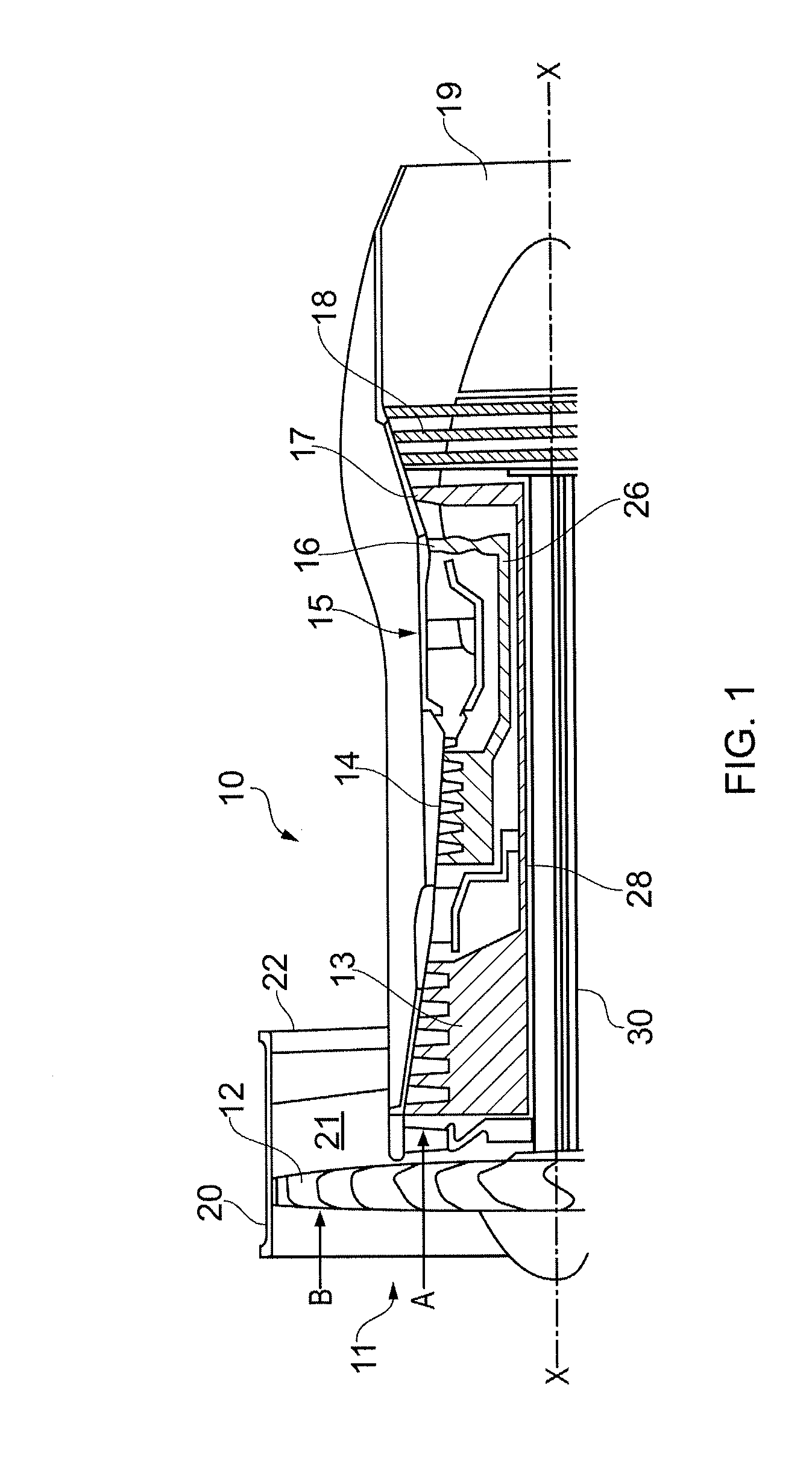
[0108]A turbofan gas turbine engine 10, as shown in FIG. 1, comprises in flow series an intake 11, a fan 12, an intermediate pressure compressor 13, a high pressure compressor 14, a combustion chamber 15, a high pressure turbine 16, an intermediate pressure turbine 17, a low pressure turbine 18 and an exhaust 19. The high pressure turbine 16 is arranged to drive the high pressure compressor 14 via a first shaft 26. The intermediate pressure turbine 17 is arranged to drive the intermediate pressure compressor 13 via a second shaft 28 and the low pressure turbine 18 is arranged to drive the fan 12 via a third shaft 30. The fan 12 is arranged within a fan casing 20 which defines a fan, or bypass, duct 21 and the fan duct 21 has a fan exhaust 22. In operation air flows into the intake 11 and is compressed by the fan 12. A first portion of the air A flows through, and is compressed by, the intermediate pressure compressor 13 and the high pressure compressor 14 and is supplied to the comb...


PUM


Abstract

A combustion chamber comprises an upstream ring structure, a downstream ring structure and a plurality of circumferentially arranged combustion chamber segments. Each combustion chamber segment extends the full length of the combustion chamber. Each combustion chamber segment comprises a frame structure and at least an inner wall and the frame structure and the inner wall are integral. An upstream end of each combustion chamber segment is secured to the upstream ring structure and a downstream end of each combustion chamber segment is mounted on the downstream ring structure. The combustion chamber segments are manufactured by additive layer manufacture. The combustion chamber segments have a stiff frame structure which carries the structural loads, the thermal loads, surge loads and flameout loads and the frame structure distributes loads into adjacent components.

Description

FIELD OF THE INVENTION[0001]The present disclosure relates to a combustion chamber and a combustion chamber segment and in particular to a gas turbine engine combustion chamber and a gas turbine engine combustion chamber segment.BACKGROUND TO THE INVENTION[0002]Currently each gas turbine engine combustion chamber wall comprises an outer wall and an inner wall. The outer wall either comprises a fabricated sheet metal wall or a forged and machined wall. The inner wall comprises a plurality of cast metal tiles which are secured onto the outer wall using threaded studs, washers and nuts. The cast metal tiles either comprise a plurality of pedestals, projections or ribs on their outer, cooler, surface to provide convection cooling of the tiles or the cast metal tiles are provided with a plurality of apertures which extend from their outer, cooler, surface to their inner, hotter, surface to provide effusion cooling of the tiles. In both arrangements coolant is supplied through apertures i...

Claims


Application Information

Patent Timeline
Patent Type & Authority Applications(United States)
IPC IPC(8): F23R3/00F02C7/20
CPCF02C7/20F23R3/002F23R2900/00018F23R2900/03041F23R2900/03043F23R2900/03044F23M2900/05005F23R3/60F23R2900/00012F23R2900/00017F23M5/04
Inventor HARDING, STEPHEN CHARLESHUCKER, PAUL ALLANRALLO, GIUSEPPE
Owner ROLLS ROYCE PLC
Why Eureka
Try Eureka