Expendable sonobuoy flight kit with aerodynamically assisted sonobuoy separation

a sonobuoy and flight kit technology, applied in the field of deployment of sonobuoys, can solve the problems of still remains a risk to flight crews, and large complex and expensive vehicles (the cruise missiles), and achieve the effect of inexpensively augmenting the coverage of existing aircra

Inactive Publication Date: 2007-08-28
BILYK DEREK +2
View PDF10 Cites 24 Cited by
  • Summary
  • Abstract
  • Description
  • Claims
  • Application Information

AI Technical Summary

Benefits of technology

[0010]The invention is a device used to retrofit existing, unmodified navy sonobuoys to enable them to self-deploy in an aircraft-like flight from a ship to a remote location. This invention provides a safer means of sonobuoy or other payload deployment in situations in which a significant threat to manned aircraft exists. Even if the threat to aircraft is low, this invention can inexpensively augment the coverage of existing aircraft, or free them to perform other duties. Furthermore, this invention gives sonobuoy deployment capability to ships without onboard aircraft. In addition, since a single ship may launch multiple sonobuoys in sequence and in different directions using this invention, several sonobuoys can enter the water at different locations almost simultaneously, rapidly forming an anti-submarine protection fence. Furthermore, the use of an autonomous on-board control system on the invention means that no personnel are required to pilot the invention to the target location.
[0011]The invention makes use of the sonobuoy itself as the central structural load-bearing member of a flying assembly. It consists of aerodynamic surfaces to provide lift and stability in flight, a propulsion system consisting of an electric motor driven propeller and single use battery, control surfaces and control surface actuators, such as servos, and an on-board control system that provides navigation and control signals to the invention. The concept is analogous to the way in which ‘smart-bombs may use a regular ’ dumb-bombs as the core of the system, but add guidance package components at the front and / or rear extremities of the weapon. In other words, the components of the flight kit are made to assemble onto an existing sonobuoy, and without the sonobuoy's presence, the invention does not constitute a flight vehicle. Desired co-ordinates for sonobuoy deployment can be entered into the on-board control system, and using a satellite navigation method (such as the use of received GPS signals for navigation), or a magnetic heading-based method, or an inertial-navigation based method, or a combination of these methods, the on-board control system provides the control signals to steer the aircraft to the target. At, or at an acceptable proximity to the sonobuoy deployment co-ordinates, the sonobuoy is separated from the other components of the flying assembly. Both the sonobuoy and the other components, which do not form a flyable assembly without the presence of the sonobuoy, fall and enter the water separately so as not to interfere with, or become entangled with, the sonobuoy. The invention's flight control system may optionally have a wireless communications link so that the sonobuoy deployment co-ordinates may be updated while the invention is in flight, or so that the invention may report the exact coordinates of a successful delivery of the sonobuoy. The invention may be stored either fully assembled onto a sonobuoy, or in a disassembled state in order to save room. In addition, the invention may make use of an aerodynamically-driven actuation method in order to assist in separating the sonobuoy from the other components of the flying assembly. Normally, the wings of a rigid-wing aircraft are connected to the fuselage of an aircraft in such a way that the lift force on the wings is resisted by a connection between the wings and the fuselage that keeps the wings in approximately the same position and orientation relative to the fuselage. However, the invention is novel in that, at the time of sonobuoy separation, the wings are permitted to rotate upward (about a hinge-axis) that is a) at or near to the point where the left wing meets the right wing, and b) oriented approximately parallel to the direction of travel, in such a way that the wing tips will come together above the sonobuoy. The invention mechanically couples this aerodynamically-driven motion to assist in separating the sonobuoy from the other flight-kit components.
[0012]The invention differs from the prior methods of sonobuoy delivery in that it recognizes that sonobuoys themselves are built very strongly, and as such have the ability to act as a primary load-carrying structural member of a flying device. In this way, rather than simply carrying the sonobuoy as a passenger (as has been proposed in methods in which the sonobuoy is deployed by recoverable UAVs or drones), the sonobuoy is used as the central structural load-bearing member of the complete flight kit. The result is that the assembled flight kit plus sonobuoy may be lighter and more compact than a complete sonobuoy-carrying UAV or drone built of similar materials and layout that only carries the sonobuoy and does not incorporate it as a part of the structure. This weight savings coupled with the fact that the flight kit does not need to retain enough on-board energy to return to a recovery point after dropping the sonobuoy potentially gives the invention greater than twice the range of a similarly sized and powered recoverable UAV.
[0013]The invention utilizes an electric motor and single use battery. This makes for simple, quiet, reliable, push-button operation and removes the need for starting equipment, fuel and lubrication that are required for fuel burning engines.

Problems solved by technology

Although the performance of these manned aircraft is effective, there still remains a risk to the flight crew when deploying sonobuoys in areas where an enemy threat exists at the desired sonobuoy drop location, such as over water near a hostile coastline.
To address this problem, there have been experimental uses of a small number of unmanned air vehicles over the last few decades for the delivery of sonobuoys from a ship to a remote location, but these vehicles are large and expensive, and as such they must retain sufficient energy on-board after deploying the sonobuoys to return to the ship to be recovered.
U.S. Pat. No. 6,498,767 to Carreiro describes a method of delivering sonobuoys by adapting them to be deployed by a cruise missile, in turn requiring a large complex and expensive vehicle (the cruise missile) to deliver multiple sonobuoys.

Method used


Image

  • Expendable sonobuoy flight kit with aerodynamically assisted sonobuoy separation
  • Expendable sonobuoy flight kit with aerodynamically assisted sonobuoy separation
  • Expendable sonobuoy flight kit with aerodynamically assisted sonobuoy separation

Examples


Embodiment Construction

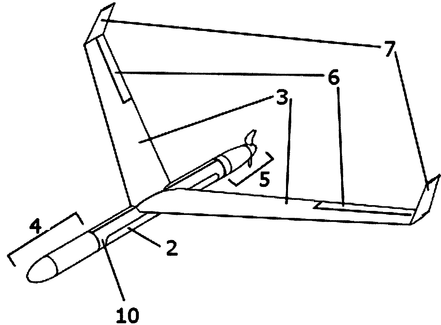
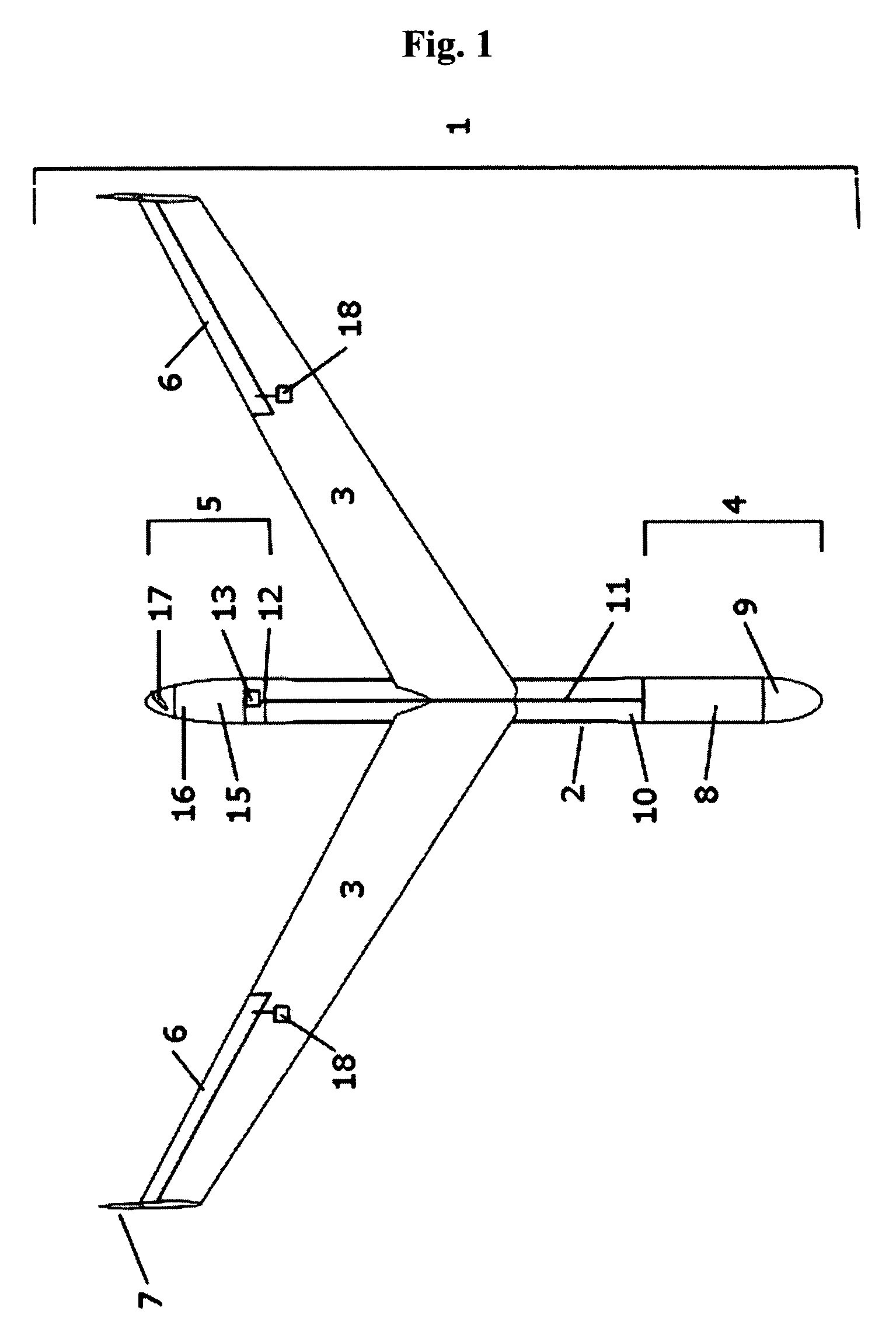
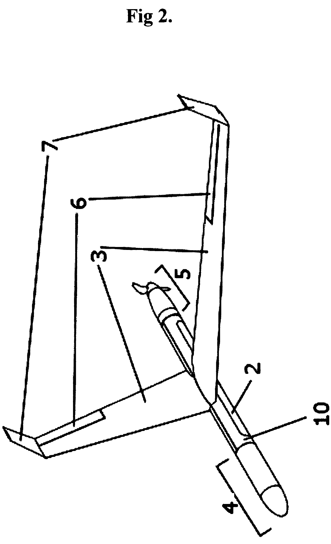
[0018]With reference to the drawings, the preferred embodiment of the invention (1) contains a standard Naval A-size sonobuoy (2) being the primary structural member onto which is attached the wings (3), a module forward of the sonobuoy (4) and a module aft of the sonobuoy (5). The wings (3) provide the requisite lift and through sweepback and twist also afford static stability in the usual manner for tailless designs. The invention need not be tailless but could be any aircraft configuration without violating the spirit of the invention, including a conventional tail aft design, canard design, tandem wing or joined wing design as it is not the configuration of the aerodynamic surfaces which sets this invention apart. The tailless design, however, is used as the preferred embodiment for the rest of this description. The flight control surfaces are of the standard type. While a full suite of pitch, yaw and roll controls may be used, a minimum configuration is desirable to reduce cost...


PUM


Abstract

A flight kit that can be retrofitted to existing navy sonobuoys. The preferred embodiment gives sonobuoys the capability of self-deployment, allowing them to be sent to a location remotely without the use of manned aircraft or recoverable unmanned air vehicles. This capability is advantageous in instances where it is desired to place a sonobuoy in an area hostile or hazardous to manned aircraft. The preferred embodiment is an attachment of a GPS navigation and control system, wings, control surfaces, and a propulsion system, onto a naval size-A sonobuoy, using the sonobuoy as the central structural load-bearing component of the assembly. The invention navigates from a launch point on a ship to a designated position, where the sonobuoy separates from the invention, using the wings' aerodynamic forces to mechanically assist in separating the sonobuoy from the flight kit. The sonobuoy and the flight kit enter the water separately to ensure no interference with the sonobuoy.

Description

BACKGROUND OF THE INVENTION[0001]1. Field of the Invention[0002]The present invention relates to the deployment of sonobuoys, more particularly to a device that enables the deployment of sonobuoys by air from a ship without the need of a manned or recoverable unmanned aircraft.[0003]2. Description of the Prior Art[0004]Sonobuoys have been used for decades as a method of tracking and detecting submarines, relying on acoustic sensors to detect submarine noises. Currently, these expendable devices are deployed from helicopters or fixed wing aircraft. Although the performance of these manned aircraft is effective, there still remains a risk to the flight crew when deploying sonobuoys in areas where an enemy threat exists at the desired sonobuoy drop location, such as over water near a hostile coastline. To address this problem, there have been experimental uses of a small number of unmanned air vehicles over the last few decades for the delivery of sonobuoys from a ship to a remote loca...

Claims


Application Information

Patent Timeline
Patent Type & Authority Patents(United States)
IPC IPC(8): F42B17/00B63B22/00B64D17/00
CPCB63B22/003F42B10/04F42B12/58F42B15/01F42B15/08F42B15/10F42B15/36F42B15/22
Inventor BILYK, DEREKZDUNICH, PATRICKMACMASTER, MARC
Owner BILYK DEREK
Why Eureka
Try Eureka