Variable displacement compressor

a compressor and variable displacement technology, applied in the direction of positive displacement liquid engines, pump control, machines/engines, etc., can solve the problems of reducing the durability of the compressor, lubricating the oil supplied to the front and not being able to lubricate the bearing and the seal devi

Inactive Publication Date: 2009-05-12
TOYOTA IND CORP
View PDF46 Cites 23 Cited by
  • Summary
  • Abstract
  • Description
  • Claims
  • Application Information

AI Technical Summary

Benefits of technology

[0008]Accordingly, it is an object of the present invention to provide a variable displacement compressor that lubricates the interior of a compressor in a desirable manner and controls the proportion of lubricating oil in an external refrigerant circuit in a satisfactory manner.

Problems solved by technology

Therefore, the lubricating oil supplied to the front bearing and the seal device by the blow-by gas will become insufficient, and the bearing and the seal device may not be sufficiently lubricated.
As a result, in a clutchless compressor that substantially stops operating when the displacement is minimal, the durability of the compressor may be decreased.
This will increase the proportion of the lubricating oil in the refrigerant gas circulating through an external refrigerant circuit and decrease the heat exchange efficiency of an expansion device.
As a result, the cooling capacity of an air conditioner will be decreased.

Method used


Image

  • Variable displacement compressor
  • Variable displacement compressor
  • Variable displacement compressor

Examples


Embodiment Construction

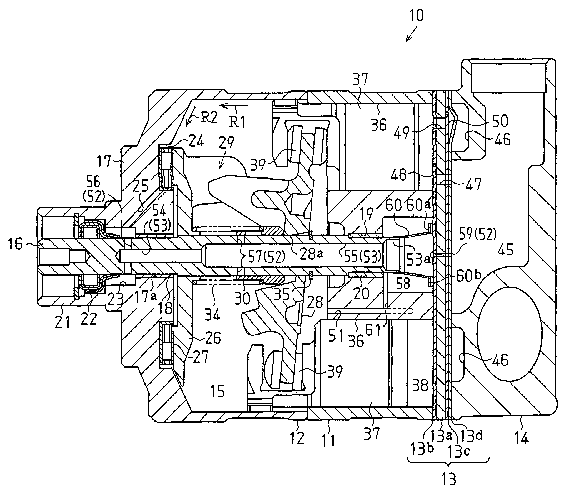
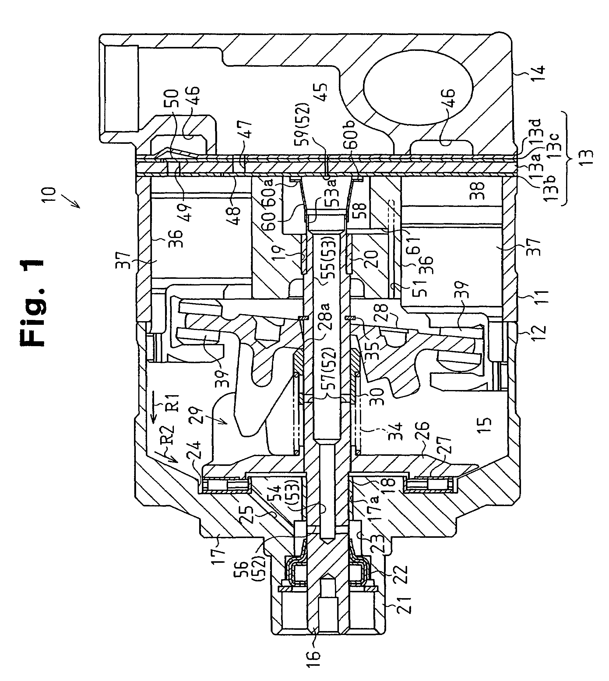
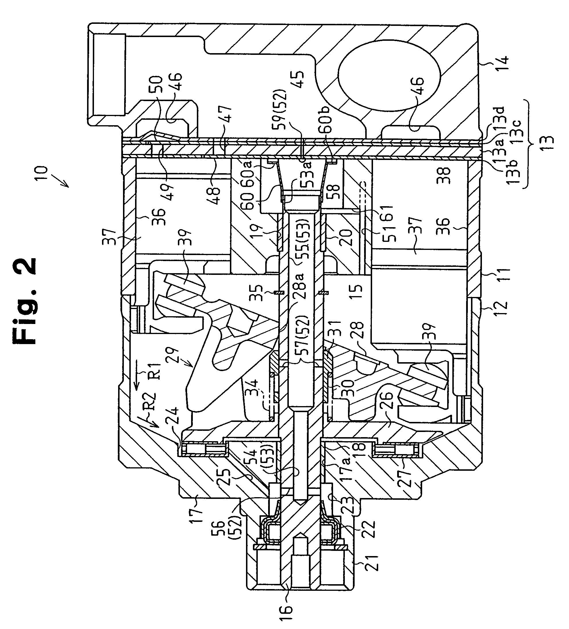
[0024]A clutchless variable displacement compressor 10, for use in a vehicle air conditioner, according to a preferred embodiment of the present invention will now be described with reference to FIGS. 1 to 6.

[0025]FIG. 1 is a cross-sectional view showing a variable displacement compressor (hereafter, simply referred to as a “compressor”) 10. The left side as viewed in FIG. 1 corresponds to the front of the compressor 10, and the right side corresponds to the rear of the compressor 10.

[0026]A compressor housing is formed by a cylinder block 11, a front housing 12 coupled to the front end of the cylinder block 11, and a rear housing 14 coupled to the rear end of the cylinder block 11 with a valve / port plate 13 arranged therebetween

[0027]A crank chamber 15 is defined between the cylinder block 11 and the front housing 12. A drive shaft 16 is rotatably supported in the crank chamber 15. The drive shaft 16 is connected to a vehicle engine (not shown). A support hole 17a extends through a...


PUM


Abstract

A variable displacement compressor including a drive shaft through which a gas passage extends between front and rear ends of the drive shaft. The gas passage is connected to a suction chamber at the rear end of the drive shaft. The drive shaft includes a first gas inlet passage, which connects the gas passage to a crank chamber through a lip seal, an oil chamber, and a thrust bearing, and a second gas inlet passage, which connects the gas passage to a central portion of the crank chamber. The drive shaft further includes a sleeve movable along the drive shaft as a swash plate inclines to adjust an open amount of the second gas inlet passage in accordance with the inclination angle of the swash plate, that is, the displacement of the compressor.

Description

BACKGROUND OF THE INVENTION[0001]The present invention relates to a piston type variable displacement compressor.[0002]Japanese Patent Laid-Open Publication No. 11-62824 and Japanese Patent Laid-Open Publication No. 2000-297746 describe examples of various displacement compressors. According to the technology described in Japanese Patent Laid-Open Publication No. 11-62824, a sleeve is fitted to a drive shaft to be slidable in the axial direction of the drive shaft. The sleeve is coupled to a swash plate. The sleeve moves axially along the drive shaft in accordance with the inclination angle of the swash plate. The drive shaft includes a gas passage which opens at the rear end of the drive shaft. The front end of the gas passage is connected to the interior of a crank chamber through a gas inlet passage extending through the drive shaft. The gas passage and the gas inlet passage form part of a bleed passage that connects the crank chamber to a suction chamber. The sleeve is designed ...

Claims


Application Information

Patent Timeline
Patent Type & Authority Patents(United States)
IPC IPC(8): F04B1/26
CPCF04B27/1063F04B27/109F04B27/1804F04B49/22
Inventor ITO, MASAFUMIHIBINO, SOKICHIHAYASHI, SHIROTAKAHATA, JUNICHIOHARA, TAKAYUKI
Owner TOYOTA IND CORP
Why Eureka
Try Eureka