Control valve for a device for changing the control times of an internal combustion engine

a control valve and control valve technology, which is applied in the direction of machines/engines, mechanical equipment, transportation and packaging, etc., can solve the problems of increasing the weight of the apparatus, increasing the overall cost, and difficulty in adjusting so as to increase the torsional rigidity of the adjuster and therefore its positional stability

Inactive Publication Date: 2009-05-19
SCHAEFFLER TECH AG & CO KG
View PDF10 Cites 47 Cited by
  • Summary
  • Abstract
  • Description
  • Claims
  • Application Information

AI Technical Summary

Benefits of technology

[0016]The invention is therefore based on the object of avoiding these outlined disadvantages and thus providing a hydraulic control valve, wherein it is possible to easily integrate additional components within the control valve and wherein, in an embodiment as a central valve, it does not have a detrimental effect on the costs or on the overall axial space of the camshaft adjuster.
[0019]As a result of designing the control valve with immediately adjacent operating connections and tank and pressure medium connections adjacent axially thereto, the camshaft adjuster can be formed in such that, in the axial direction, it extends only in the region of the two operating connections, so that the overall axial space of the camshaft adjuster can be reduced to a minimum.
[0020]Since the tank and the pressure medium connection are thus arranged outside the camshaft adjuster, complicated feed and discharge of the pressure medium through the output drive part of the camshaft adjuster is unnecessary, which means that the camshaft adjuster can be fabricated more economically.
[0024]Arrangement of the nonreturn valve within the control valve increases the torsional rigidity of the adjuster and therefore its positional stability.

Problems solved by technology

In this embodiment, the fact that additional components, such as filters or nonreturn valves, can be integrated within the control piston, between the pressure medium connection and the operating connections, only with difficulty, is disadvantageous.
Furthermore, in each case two of these components have to be used, which leads to higher overall costs and to an increased weight of the apparatus.
This type of valve is unsuitable specifically for the use as a central valve, in which the control valve is arranged within a central bore of the output drive part of a camshaft adjuster because the pressure medium supply and pressure medium discharge to the pressure medium connection and the tank connection, respectively, have to be carried out through the output drive part.
This results in additional costs during production of this component.
Furthermore, as a result of the arrangement of the pressure medium connection and of the tank connection between the operating connections, the minimum axial overall length of the camshaft adjuster is unnecessarily enlarged.

Method used


Image

  • Control valve for a device for changing the control times of an internal combustion engine
  • Control valve for a device for changing the control times of an internal combustion engine
  • Control valve for a device for changing the control times of an internal combustion engine

Examples


Embodiment Construction

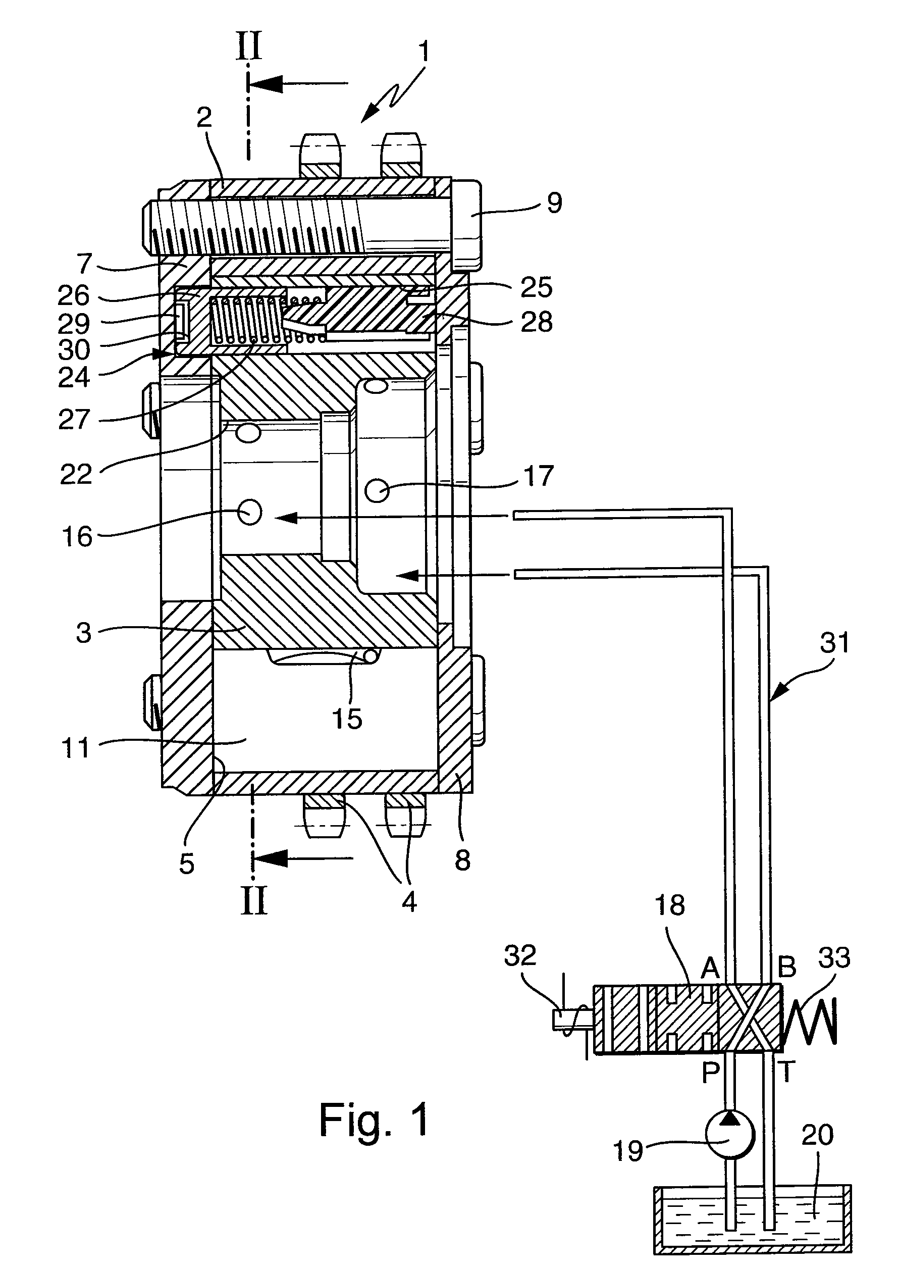
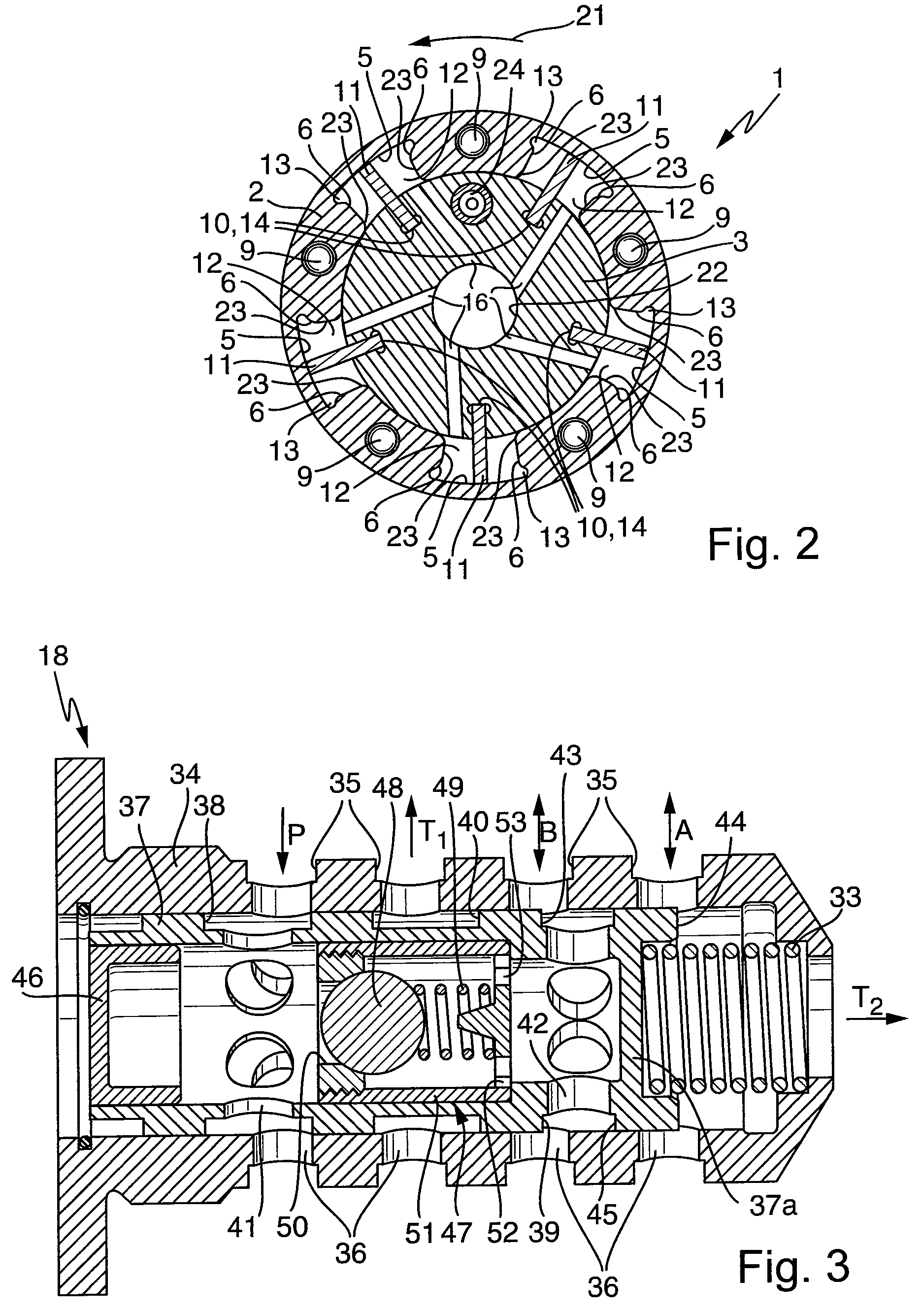
[0031]FIGS. 1 and 2 show a device 1 for changing the control times of an internal combustion engine. The device 1 substantially comprises a stator 2 and a rotor 3 arranged concentrically thereto. A drive wheel 4 is firmly connected to the stator 2 so as to rotate with it and, in the embodiment illustrated, is formed as a chain wheel. Embodiments of the drive wheel 4 as a belt or gear are likewise conceivable. The stator 2 is mounted on the rotor 3 such that the rotor can rotate with respect to the stator. Five recesses 5 spaced apart in the peripheral direction are provided on the inner peripheral surface of the stator 2 in the embodiment illustrated. The recesses 5 are delimited in the radial direction by the stator 2 and the rotor 3, in the peripheral direction by two side walls 6 of the stator 2 and in the axial direction by first and second side covers 7, 8. Each of the recesses 5 is closed in a pressure-tight manner in this way. The first and the second side covers 7, 8 are con...


PUM


Abstract

A control valve for a device for changing the control times of an internal combustion engine, having a substantially hollow-cylindrical valve housing, a control piston which is arranged within the valve housing and can be displaced axially, a pressure medium connection, two operating connections, and at least one tank connection. The operating connections, the pressure medium connection and the tank connection are formed as radial connections. It is possible for the operating connections to be connected to the pressure medium connection and the tank connection by axial displacement of the control piston within the valve housing. The operating connections are arranged adjacently.

Description

FIELD OF THE INVENTION[0001]The invention relates to a control valve for a device for changing the control times of an internal combustion engine. The valve has a substantially hollow-cylindrical valve housing, a control piston which is arranged within the valve housing and can be displaced axially, and a pressure medium connection, two operating connections and at least one tank connection. The operating connections, the pressure medium connection and the tank connection are formed as radial connections. It is possible for the operating connections to be connected to the pressure medium connection and the tank connection by axial displacement of the control piston within the valve housing.[0002]In internal combustion engines, camshafts are used to actuate the gas exchange valves. Camshafts are fitted in the internal combustion engine in such a way that cams fitted to them bear on cam followers, for example bucket tappets, drag levers or rocking levers. If a camshaft is set rotating...

Claims


Application Information

Patent Timeline
Patent Type & Authority Patents(United States)
IPC IPC(8): F15B13/044F01L1/344F01L1/34F15B13/04
CPCF01L1/022F01L1/34F01L1/344F01L1/3442F01L1/024F01L1/026F01L2001/34426F01L2001/3443F01L2001/3444F01L2001/34469Y10T137/86702
Inventor STRAUSS, ANDREASROHR, ANDREASHOPPE, JENS
Owner SCHAEFFLER TECH AG & CO KG
Why Eureka
Try Eureka