Adjustable cable hanger for a bicycle

Inactive Publication Date: 2009-05-19
TIEN HSIN INDS
View PDF4 Cites 4 Cited by
  • Summary
  • Abstract
  • Description
  • Claims
  • Application Information

AI Technical Summary

Benefits of technology

[0007]The main objective of the present invention is to provide an improved cable ha

Problems solved by technology

The conventional cable hanger has some defects.
The conventional cable hanger only assembles with the cables so the cable hanger will move inadvertently or interfere with other parts by

Method used


Image

  • Adjustable cable hanger for a bicycle
  • Adjustable cable hanger for a bicycle
  • Adjustable cable hanger for a bicycle

Examples


Example

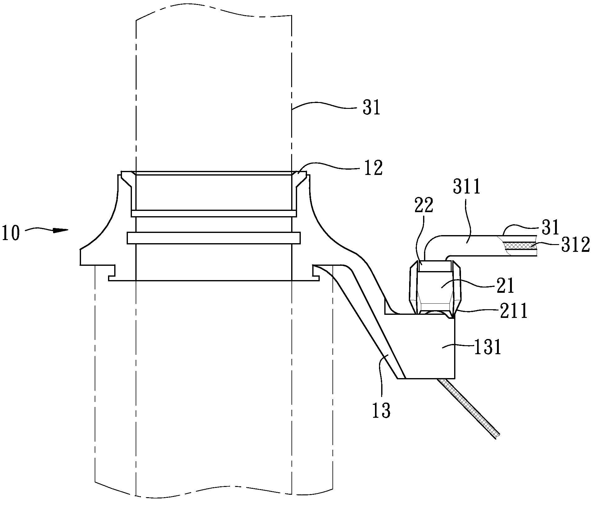
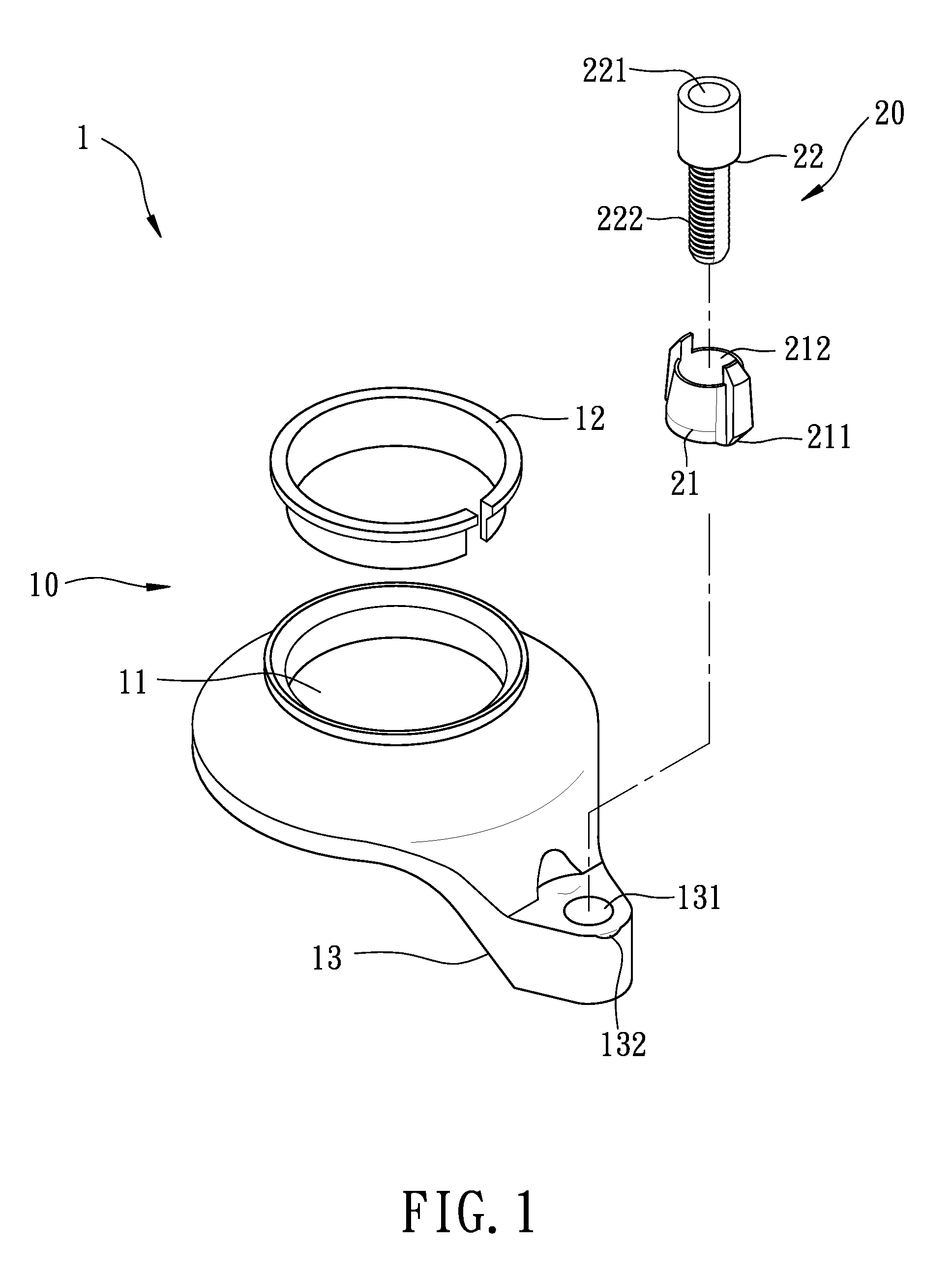
[0015]Referring to the drawings and initially to FIGS. 1-3, a cable hanger in accordance with the present invention comprises a base 10 and a adjust unit 20 connected to the base 10, wherein the adjust unit 20 is positioned be a tension of a cable that extends through the adjust unit 20, as shown in FIGS. 4 and 5.

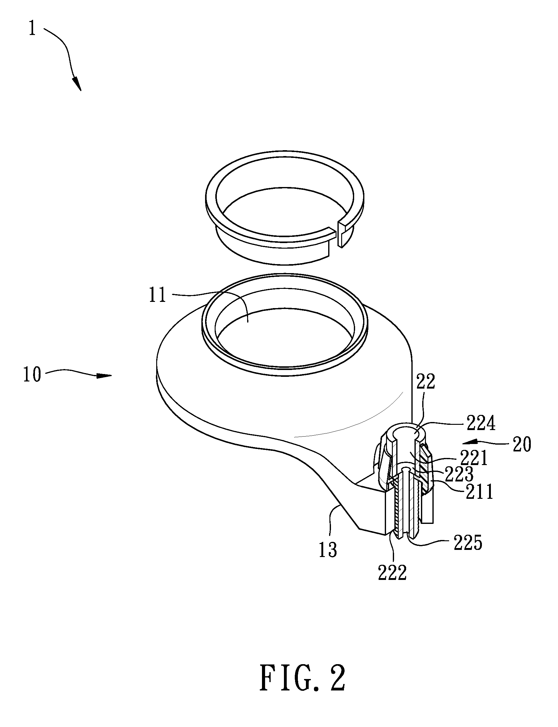
[0016]The base 10 has an opening 11 defined therein and adapted to stably sleeve on a steering tube 31 of a bicycle, and a tongue 13 outwardly extending therefrom. A locking ring 12 is mounted in the opening 11 between the base 10 and the steering tube 31 for holding the base 10 in place. In the preferred embodiment of the present invention, the base 10 is also provided as an upper cap of a headset. The tongue 13 has a round through hole 131 and at least two indentations 132 respectively defined therein, wherein the at least two indentation 132 diametrically surround the through hole 131 for selectively positioning the adjust unit 20.

[0017]The adjust unit 20 comprises an ad...


PUM

PropertyMeasurementUnit
Tensionaaaaaaaaaa

Abstract

A cable hanger includes a base having an opening defined to stably sleeve on a tube of a bicycle and an adjust unit connected to the base. The base has a tongue outwardly extending therefrom and a through hole defined in the tongue. The adjust unit comprising an adjust base and an adjuster is partially mounted in the through hole. The adjust base is mounted on the tongue and has a hole aligned with the through hole for receiving the adjuster. The adjuster has a through hole aligned with the through hole in the tongue for adapting a cable. The cable passes through the through holes in the adjuster and the tongue. A tension of the cable is adjusted by a movement of the adjuster relative to the tongue.

Description

BACKGROUND OF THE INVENTION[0001]1. Field of the Invention[0002]The present invention relates to a cable hanger, and more particularly to an adjustable cable hanger for a bicycle.[0003]2. Description of Related Art[0004]A conventional cable hanger in accordance with the prior art comprises a plate having a hole defined therethrough and a bent side extending from a lower end of said plate. Three protrusions split from said plate and define three apertures. A flange extends from a top end of said plate and two notches are defined in said flange. A positioning plate is engaged between said flange and said protrusions. A central hole is defined through said positioning plate. A bolt extends through said hole in said plate and said central hole in said positioning plate, and a nut is engaged with said bolt. Two brake cables extend through notches in the flange and are securely clamped between the positioning plate and the plate.[0005]The conventional cable hanger has some defects. The co...

Claims


Application Information

Patent Timeline
IPC IPC(8): B66D3/00
CPCB60T11/046B62L1/00Y10T403/75
Inventor CHIANG, DOUGLAS
Owner TIEN HSIN INDS
Why Eureka
Try Eureka