Backlight module

a backlight module and module technology, applied in the field of backlight modules, can solve the problems of difficult lens design, high production cost, and aggravate the problem of heat dissipation, and achieve the effect of improving the light mixing

Active Publication Date: 2009-05-19
TCL CHINA STAR OPTOELECTRONICS TECH CO LTD
View PDF5 Cites 19 Cited by
  • Summary
  • Abstract
  • Description
  • Claims
  • Application Information

AI Technical Summary

Benefits of technology

[0009]Therefore, the first object of the present invention is to provide a backlight module having an improved light mixing effect.
[0010]The second object of this invention is to provide a backlight module capable of reducing the required light mixing distance.
[0011]The third object of this invention is to provide a backlight module which can be used as a flat light source having a relatively small size.
[0012]The fourth object of this invention is to provide a backlight module which can be repaired with relative ease when necessary.
[0013]The fifth object of this invention is to provide a backlight module which can be fabricated at a relatively lower cost.

Problems solved by technology

Although the distance for mixing the lights emitted from the LEDs 1 can be reduced by decreasing distances among the LEDs 1, in this way, the number of the LEDs 1 is increased, which in turn results in higher production costs, and aggravates the problem of heat dissipation.
However, the design for the lens is difficult, and the production cost thereof is relatively high.
Furthermore, the light mixing effect achievable by the lens is limited when the arrangement density of the LEDs 1 used in the backlight module is small.

Method used


Image

  • Backlight module
  • Backlight module
  • Backlight module

Examples


Embodiment Construction

[0031]Before the present invention is described in greater detail, it should be noted that like elements are denoted by the same reference numerals throughout the disclosure.

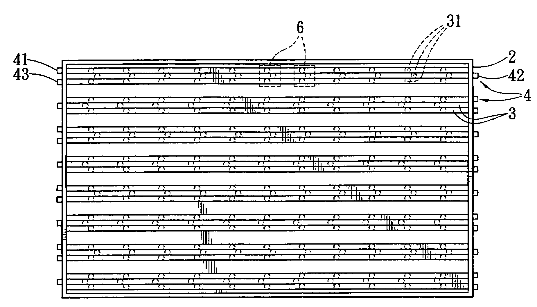
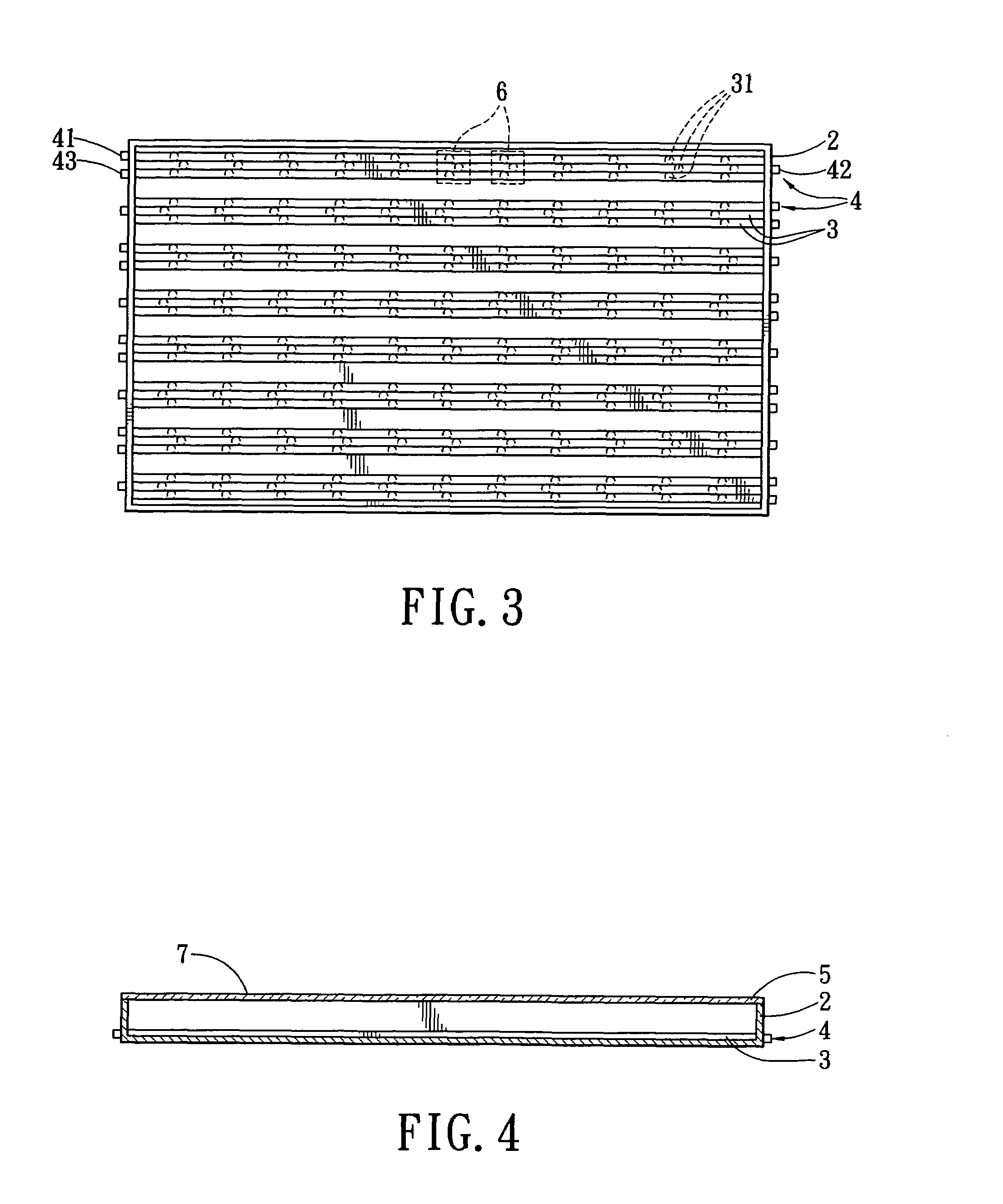
[0032]Referring to FIGS. 3 and 4, the first preferred embodiment of a backlight module according to this invention is shown to include a light box 2, a plurality of light guide tubes 3, a plurality of light sources 4, and a light diffusing member 5.

[0033]The light box 2 has a light exit side 7, and is used to receive the light guide tubes 3 therein. Preferably, a reflecting film (not shown) can be disposed in the light box 2 so as to improve the light extracting efficiency.

[0034]The light guide tubes 3 are substantially parallel to each other. Each of the light guide tubes 3 is configured as a tubular transparent body, and has a plurality of microstructures 31, which are spaced apart along a length of the light guide tube 3. The light guide tubes 3 and the microstructures 31 are disposed in the light box 2 in a ...


PUM


Abstract

A backlight module includes a light box, at least one light guide tube, and at least one light source. The light box has a light exit side. The light guide tube has a plurality of microstructures which are spaced apart along a length of the light guide tube. The light guide tube and the microstructures are disposed in the light box in a particular arrangement so that the microstructures are placed substantially in a matrix array within the light box. The light source is disposed adjacent to the light guide tube, and is operable so as to emit a light beam to the light guide tube. The microstructures disperse the light beam from the light guide tube.

Description

CROSS-REFERENCE TO RELATED APPLICATION[0001]This application claims priority of Taiwanese Application No. 094113866, filed on Apr. 29, 2005.BACKGROUND OF THE INVENTION[0002]1. Field of the Invention[0003]The invention relates to a backlight module, more particularly to a backlight module having a light emitting diode (LED) as a light source.[0004]2. Description of the Related Art[0005]Referring to FIGS. 1 and 2, there are usually two types of backlight modules, i.e., a side-edge type of backlight module, as shown in FIG. 1, and a direct type of backlight module, as shown in FIG. 2. Since a relatively long distance is required for mixing lights emitted from LEDs 1 to obtain mixed light having even brightness and color, a light box 11 of a conventional backlight module cannot be reduced in thickness advantageously.[0006]Although the distance for mixing the lights emitted from the LEDs 1 can be reduced by decreasing distances among the LEDs 1, in this way, the number of the LEDs 1 is i...

Claims


Application Information

Patent Timeline
Patent Type & Authority Patents(United States)
IPC IPC(8): F21V7/04
CPCG02B6/001G02B6/0018
Inventor CHOU, WEI-JENKANG, PO-CHUAN
Owner TCL CHINA STAR OPTOELECTRONICS TECH CO LTD
Why Eureka
Try Eureka