Magnetic disk drive with elastic support member

a magnetic disk and elastic support technology, applied in the direction of electrical apparatus construction details, instruments, record information storage, etc., can solve the problems of limited number of disks and access capability, no effect, and limited mounting space in the out-of-plane direction of the hda, so as to prevent the effect of reducing the positioning accuracy

Inactive Publication Date: 2009-05-19
WESTERN DIGITAL TECH INC
View PDF8 Cites 7 Cited by
  • Summary
  • Abstract
  • Description
  • Claims
  • Application Information

AI Technical Summary

Benefits of technology

[0012]A feature of the present invention is to provide a magnetic disk drive that improves positioning accuracy, which otherwise deteriorates due to the in-plane rotation mode of the whole magnetic disk drive as a rigid body, which is caused by disturbance or couple; the thrust mode and conical mode of the spindle, which is caused by disturbance; the case thrust coupled mode; and the case spindle fall coupled mode.
[0017]According to the present invention, it is possible to prevent the positioning accuracy from decreasing in the in-plane rotation mode of the whole magnetic disk drive as a rigid body, which is caused by disturbance or couple, in the thrust mode, and the conical mode, of the spindle, which is caused by disturbance, and in the case thrust coupled mode, the case spindle fall coupled mode, and the like.

Problems solved by technology

However, in the case of the thin-plate metal spring, no effect is produced.
Because of it, the mounting space in the out-of-plane direction of the HDA is limited.
To be more specific, possible limitations include the number of disks and the access capability because a force constant is insufficient as a VCM cannot be thickened.
Further, when a shock is given or strong vibrations are applied, buckling easily occurs because of the cylindrical shape, or the curvature shape, of the rubber / gel.
Accordingly, there is also a high possibility that a support member will be damaged.

Method used


Image

  • Magnetic disk drive with elastic support member
  • Magnetic disk drive with elastic support member
  • Magnetic disk drive with elastic support member

Examples


Embodiment Construction

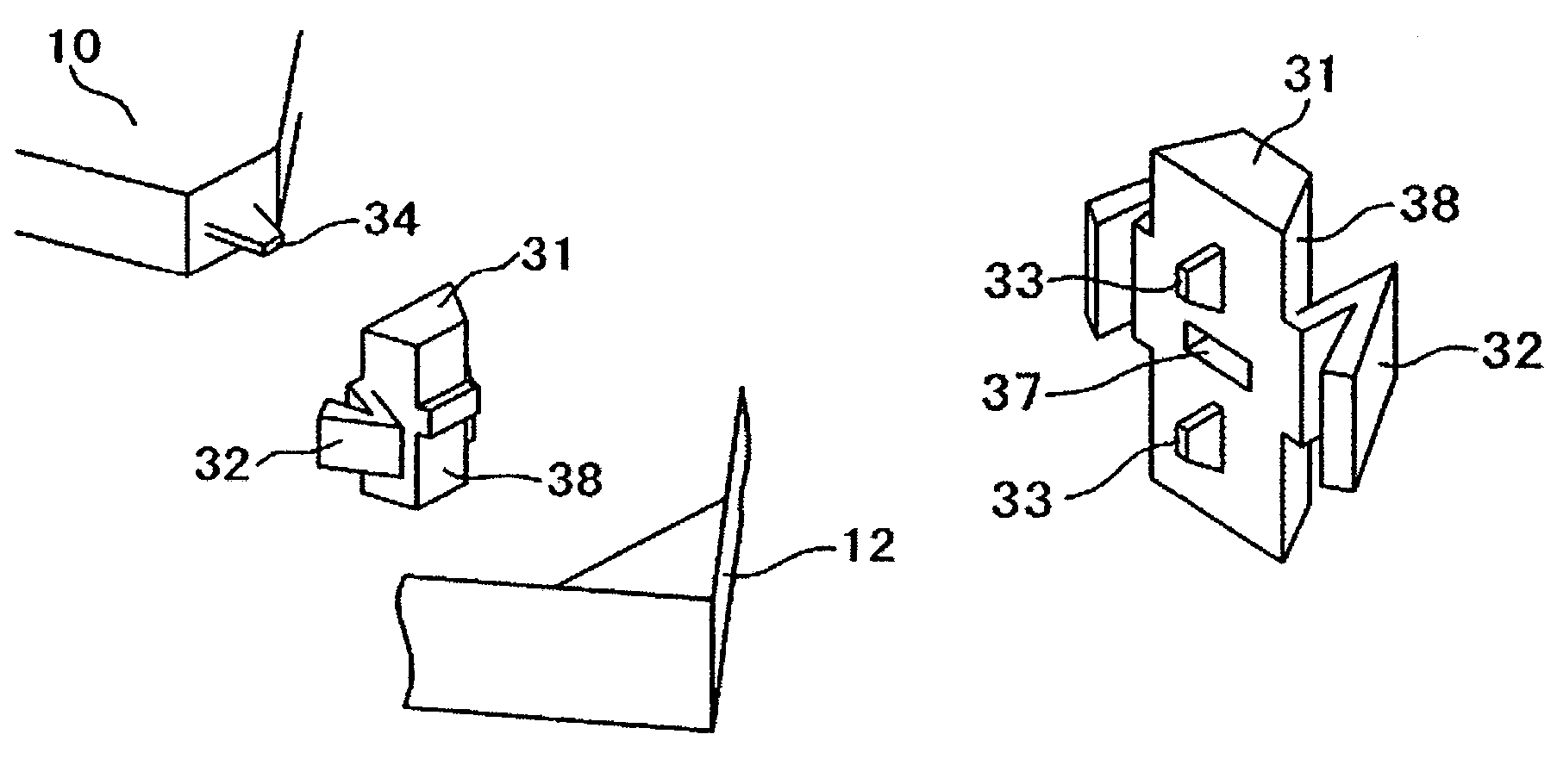
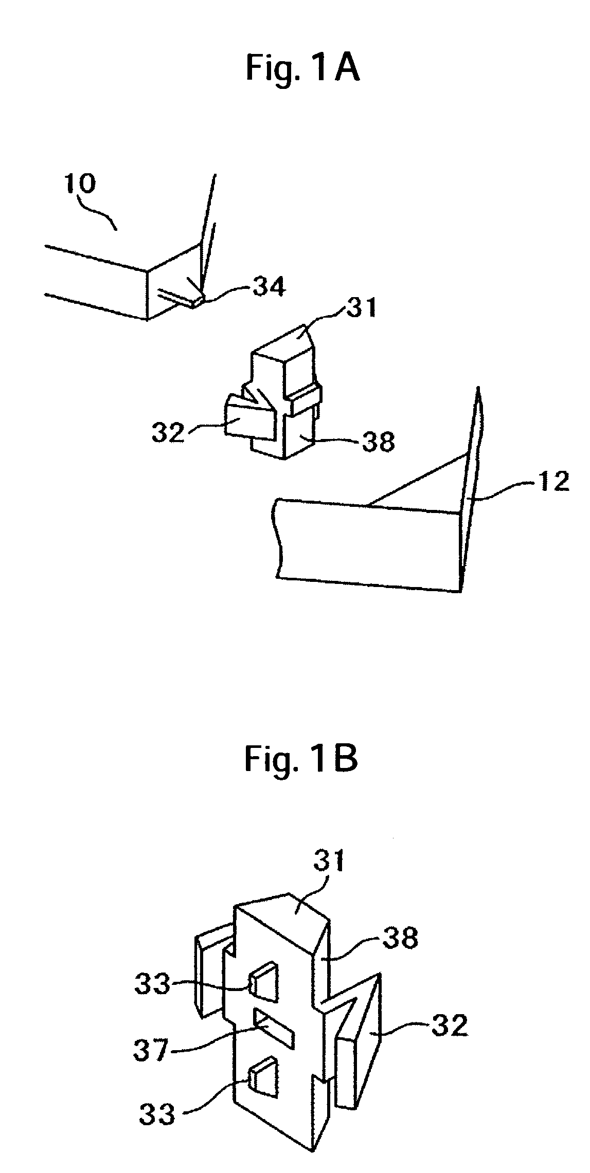
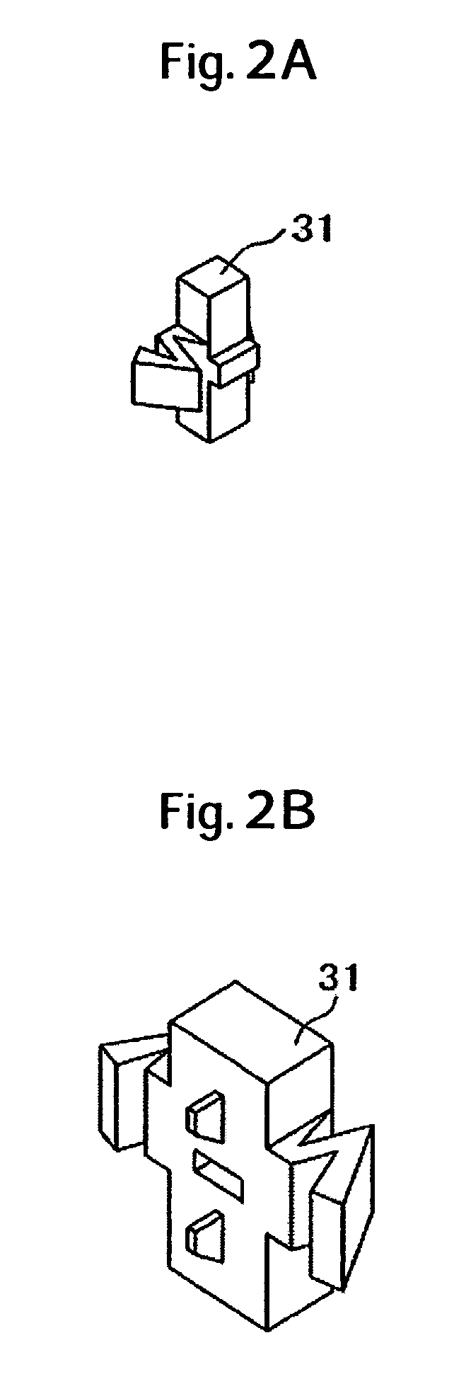
[0043]According to the present invention, for the out-of-plane direction, an HDA (Head Disk Assembly) is carried on a frame by means of compressive deformation of an elastic support member surrounded by a base and a frame of the HDA. On the other hand, for the in-plane direction, the HDA is carried on the frame by means of shear deformation. A horizontal fin-shaped member, therefore, supports the elastic support member from the base. Further, a PCB (Printed Circuit Board) is also mounted to the frame; and an electrical connection is made between the HDA and the PCB with cables, the stiffness of which is small. With this structure, the elastic support member is subjected to compressive deformation with respect to the out-of-plane direction, whereas it is subjected to shear deformation with respect to the in-plane direction. Because the stiffness of deformation is high in the order of compression, shear, and bending, a clearance between the base or the cover and the frame can be reduc...


PUM

PropertyMeasurementUnit
in-plane rotation frequencyaaaaaaaaaa
heightaaaaaaaaaa
diameteraaaaaaaaaa

Abstract

The positioning accuracy of a magnetic head decreases due to vibrations in the in-plane rotation mode of an HDD, which are caused by couple or disturbance occurring in seek operation, due to vibrations in the thrust mode, and the conical mode, of the spindle, which are caused by disturbance, and due to vibrations in the case thrust mode, the spindle fall mode, and the like. In one embodiment, an elastic support member includes a pillar-shaped part. The elastic support member is provided with a recess on a surface opposite to a corner of a base, and longitudinal fin projections on the upper and lower sides with respect to the recess. The base is provided at its corner with a horizontal fin that is parallel to a disk surface. The horizontal fin is inserted into the recess of the elastic support member. The longitudinal fin projections come into contact with the base, and control basic vibrational characteristics on both the upper and lower sides with respect to the horizontal fin. The pillar-shaped part is provided with a zigzag-shaped part so that the pillar-shaped part may come into contact with a frame.

Description

CROSS-REFERENCES TO RELATED APPLICATIONS[0001]This application claims priority from Japanese Patent Application No. JP2005-000509, filed Jan. 5, 2005, the entire disclosure of which is incorporated herein by reference.BACKGROUND OF THE INVENTION[0002]The present invention relates to a magnetic disk drive, and more particularly to an improvement in positioning accuracy of a magnetic head with couple and disturbance occurring in seek operation of the magnetic disk drive.[0003]In recent years, an improvement in recording density of a magnetic disk drive is required to increase the storage capacity thereof. For this purpose, it is important to increase the positioning accuracy of the magnetic head. However, there are various factors that obstruct the improvement in positioning accuracy. The obstruction factors include: a positioning error caused by the force of air during the rotation of a disk; a positioning error caused by vibrations of a mechanical system as a result of positioning o...

Claims


Application Information

Patent Timeline
Patent Type & Authority Patents(United States)
IPC IPC(8): G11B33/08
CPCG11B25/043G11B33/08
Inventor SEGA, MASAHIKONAGAHIRO, SHINKANEKO, JIRONAKAMURA, GENTAROU
Owner WESTERN DIGITAL TECH INC
Why Eureka
Try Eureka