Low-obscuring tile installation spacer

a tile installation and low-obscurity technology, applied in the field of tile installation, can solve the problems of difficult handling of spacers, difficult use of tape measures or other devices, and inability to accurately locate tiles,

Inactive Publication Date: 2009-05-26
TAVY ENTERPRISES
View PDF12 Cites 41 Cited by
  • Summary
  • Abstract
  • Description
  • Claims
  • Application Information

AI Technical Summary

Benefits of technology

[0022]The size and shape of the base are not critical, but should generally be sized and shaped to render their use convenient in tile setting operations. For example, the thickness of the base can be 1 / 16 of an inch. The size of the devices should be sufficiently large that the devices can be manipulated by workers who may have gloved or heavily calloused hands. The overall size of the devices should also be sufficiently small that a plurality of the devices can be used to space the tiles on a surface without the devices placed in adjacent tile joints interfering with the operation of one another. For example, generally disc-shaped devices having an outside diameter of about 1⅛ inches are convenient, and still larger devices remain convenient. The shape of the base should extend beyond the spacer in at least one direction, so that the device does not fit entirely within a tile joint in its normal operation. The outermost portion of the base can extend to the outermost dimension of a spacer or beyond. Alternatively, the outermost dimension of the spacer can extend beyond the outermost portion of the base. The base can be shaped and dimensioned to permit most of the area of the base to define a window extending therethrough. Preferably, the base has a width (parallel to the face of the tiles being spaced when the device is set between two tiles) that has sufficient rigidity to prevent easy deformation or shifting of the spacer in the course of normal manipulation of tiles, such as a minimum width of about 1 / 16 of an inch for devices having a base made from low density polyethylene.
[0045]The material must be sufficiently rigid that the device will not melt, bend easily, compress easily, or otherwise deform under the stresses normally incident to tile installation operations. Semi-rigid, or even rubbery, devices can be used, and the non-brittleness of such materials can beneficially affect their durability. The material is preferably selected such that it can be cut using tools (e.g., pocket knives, scissors, snips, etc.) available to a tile setter. Such a choice of materials permits customization of the device described herein for use in particular tile setting situations peculiar to many tile setting jobs (e.g., setting of tiles around an obstruction in an otherwise-flat surface). The material is also preferably a material having a specific density less than that of water, so that the devices described herein will float on water (e.g., in a bucket of water used by a tile setter). Devices that float in water can also be conveniently cleaned (e.g., by agitating water in which the devices are floating).

Problems solved by technology

Tape measures or other devices are difficult to use and precise tile location marks are often less than accurate.
Most tile layers have large, heavily callused fingers and find the spacers hard to handle.
When working with the spacers, it is difficult to handle them and move them around.
Additionally, they provide no guide to the depth of the lay of the tiles (the uniformity of the final finish across several tiles) as the job proceeds.
A criticism leveled by some, particularly non-professional, tile setters is that portions of known tile spacers can obscure their ability to visually confirm that they have correctly aligned edges and corners of tiles using the spacers.

Method used


Image

  • Low-obscuring tile installation spacer
  • Low-obscuring tile installation spacer
  • Low-obscuring tile installation spacer

Examples


example

[0055]The subject matter of this disclosure is now described with reference to the following Example. This Example is provided for the purpose of illustration only, and the disclosure is not limited to this Example, but rather encompasses all variations which are evident as a result of the teaching provided herein.

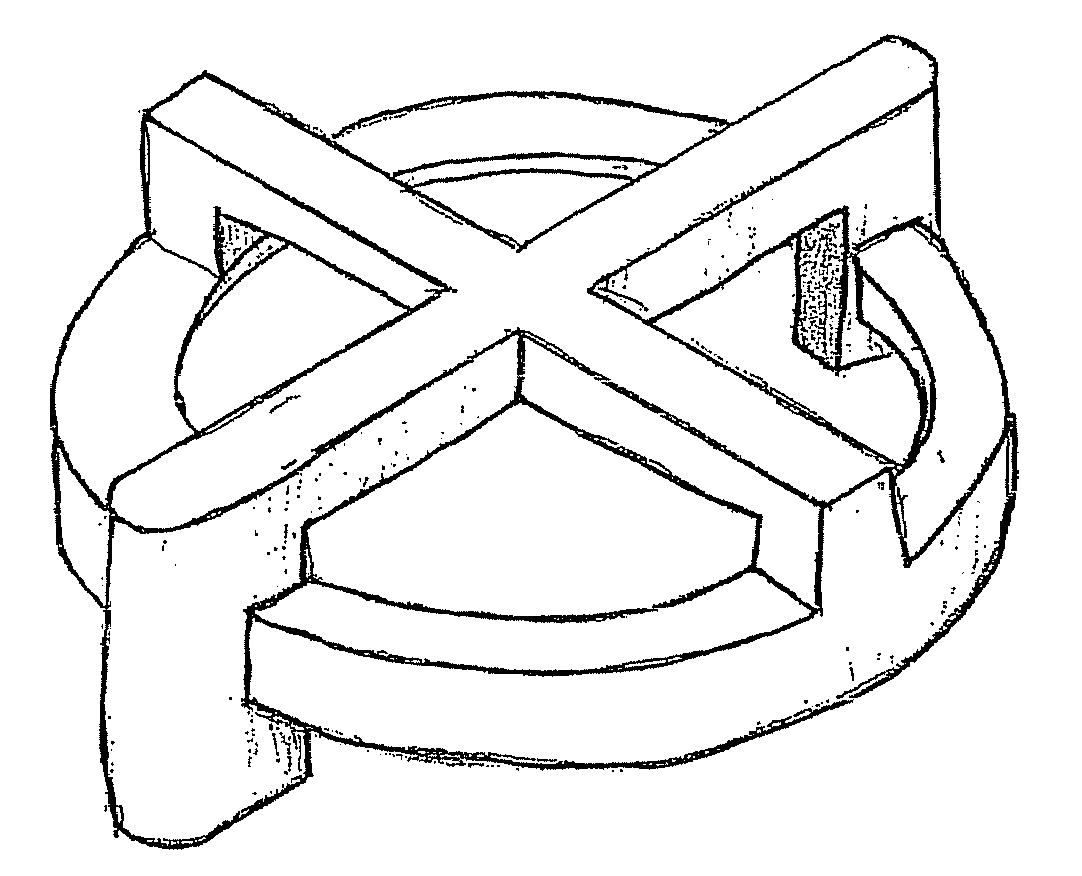
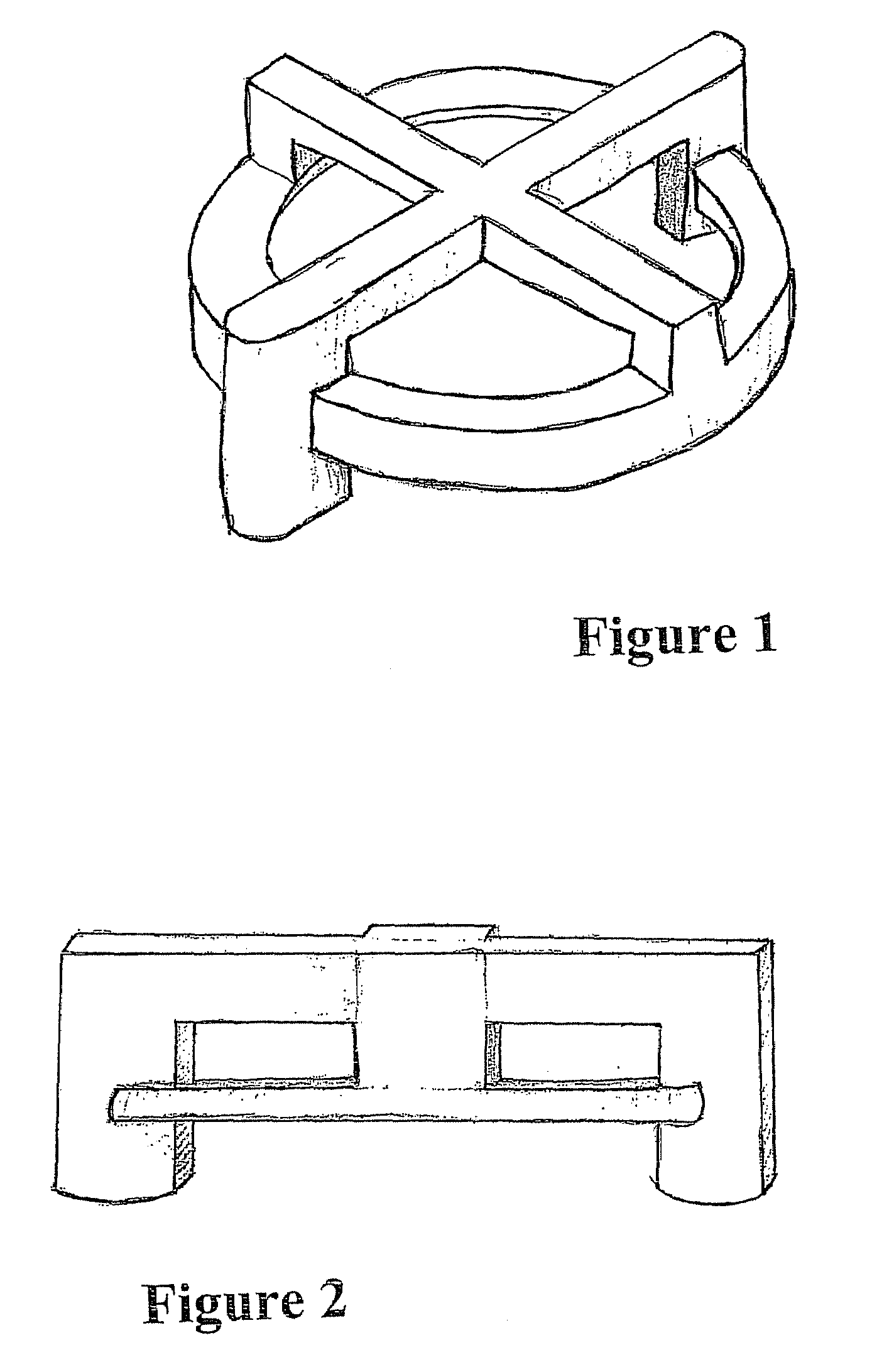
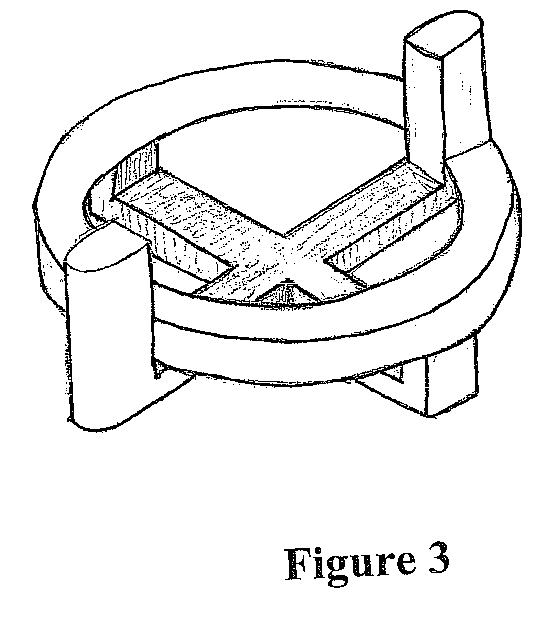
[0056]One example of a device described herein is illustrated in FIGS. 1, 2, and 3. In this embodiment, the base is disk-shaped and has a large concentric circular window, which is a substantially concentric void in the central portion of the base. The device has a straight spacer affixed to one face of the base, and a cross-shaped (corner) spacer is affixed to the opposite face. The window extends through the straight spacer leaving two block-like structures, each having a rounded outer edge extending across the remaining surface of the base. The corner spacer bridges the window in a plane parallel to but not coplanar with the base. The base and spacers are monolithic, an...


PUM


Abstract

The disclosure relates to tile-spacing devices for spacing tiles apart from one another during their installation, so as to create a space between the tiles, such as a space into which a grout, mortar, sealant, or other material can be inserted. Like previous tile-spacing devices, the devices described herein include one or more spacers disposed on a base. However, unlike previous devices, the devices described herein have a window that extends through the base, through which engagement of at least one of the tiles with the edge of a spacer can be visually observed.

Description

BACKGROUND[0001]The disclosure relates generally to the field of tile installation. Commonly installed tiles include those made of ceramic, stone, wood, webbed mosaic, and other materials. Tile installation spacers are widely used by both professionals and novices for maintaining adequate and consistent spacing between tiles.[0002]In the process of covering floor, wall and counter surfaces with ceramic tile and the like, individual tiles, or sheets of mosaic glued to a mesh webbing, are individually set into either some form of adhesive, or some form of mortar. In the process of setting the individual pieces, it is known to use tile spacers to assist in achieving uniformly sized grout spacing between the tiles or sheets of mosaic. These are typically in the shape of a cross, so as to define a corner where four tiles will intersect. One leg of the cross can be cut off, making a T spacer, which can be used when an offset layout is utilized, with T-shaped grout spaces at the intersecti...

Claims


Application Information

Patent Timeline
Patent Type & Authority Patents(United States)
IPC IPC(8): G01B3/30G01D21/00
CPCE04F21/0092
Inventor TAVY, ARMENTAVSHANJIAN, KEITH
Owner TAVY ENTERPRISES
Why Eureka
Try Eureka