Piezoelectric inkjet printhead and method of manufacturing the same

a technology of inkjet printhead and manufacturing method, which is applied in the field of inkjet printhead, can solve the problems of non-smooth ink flow, complicated manufacturing process of inkjet printhead, and increase in alignment errors, and achieve the effect of preventing cross-talk and being simple to constru

Inactive Publication Date: 2009-05-26
SAMSUNG ELECTRO MECHANICS CO LTD
View PDF12 Cites 8 Cited by
  • Summary
  • Abstract
  • Description
  • Claims
  • Application Information

AI Technical Summary

Benefits of technology

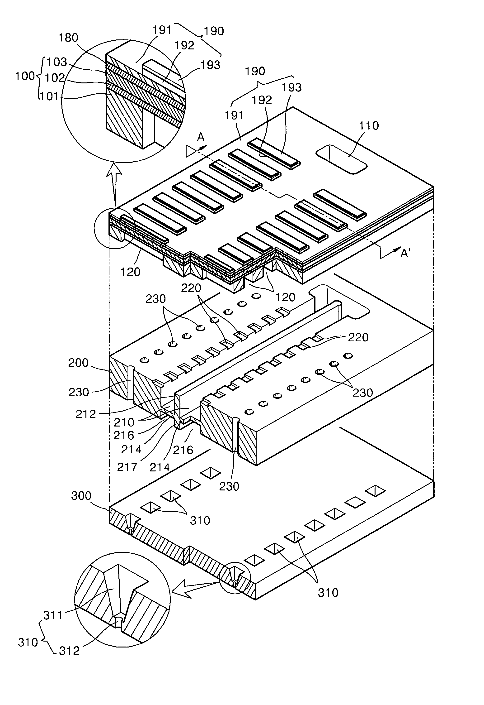
[0020]It is therefore a feature of an embodiment of the present invention to provide a piezoelectric inkjet printhead that includes a damping membrane formed under a manifold to dampen a sudden pressure change inside the manifold for preventing cross-talk when ink is ejected, and a method of manufacturing the piezoelectric inkjet printhead.
[0021]It is another feature of an embodiment of the present invention to provide a piezoelectric inkjet printhead, and a method of manufacturing the piezoelectric inkjet printhead, that is simpler to construct.

Problems solved by technology

Since the plurality of thin plates is aligned through many operations, alignment errors increase and the manufacturing process of the inkjet printhead is complicated.
The alignment errors cause non-smooth ink flow and lower the ink ejecting performance of the inkjet printhead.
The precise aligning may increase the price of the printhead.
In addition, since the thin plates of the printhead are formed of different materials using different methods, the manufacturing process of the printhead is complicated and it is difficult to bond the thin plates, thereby decreasing the yield of the printhead.
Further, since the thin plates of the printhead are formed of different materials, the alignment of the thin plates may be distorted or the thin plates may be deformed according to temperature changes due to different thermal expansion characteristics of the thin plates, even if the thin plates are precisely aligned and bonded together in manufacturing process.
If cross-talk occurs when ink is ejected as described above, ink ejecting speed and volumes of ink droplets vary undesirably.
However, when ink is ejected through a plurality of nozzles, as shown in the right side of FIG. 4, the ejected ink droplets do not reach a desired position indicated by a solid line due to cross-talk between the nozzles.
As described above, if cross-talk occurs when ink is ejected, ink cannot be ejected uniformly, thus decreasing printing quality.

Method used


Image

  • Piezoelectric inkjet printhead and method of manufacturing the same
  • Piezoelectric inkjet printhead and method of manufacturing the same
  • Piezoelectric inkjet printhead and method of manufacturing the same

Examples


Embodiment Construction

[0051]Korean Patent Application No. 10-2005-0013141, filed on Feb. 17, 2005, in the Korean Intellectual Property Office, and entitled: “Piezoelectric Inkjet Printhead and Method of Manufacturing the Same,” is incorporated by reference herein in its entirety.

[0052]The present invention will now be described more fully hereinafter with reference to the accompanying drawings, in which exemplary embodiments of the invention are shown. The invention may, however, be embodied in different forms and should not be construed as limited to the embodiments set forth herein. Rather, these embodiments are provided so that this disclosure will be thorough and complete, and will fully convey the scope of the invention to those skilled in the art. In the figures, the dimensions of layers and regions are exaggerated for clarity of illustration. It will also be understood that when a layer is referred to as being “on” another layer or substrate, it can be directly on the other layer or substrate, or ...


PUM


Abstract

A piezoelectric inkjet printhead, and a method of manufacturing the same, includes an ink inlet for allowing inflow of ink, a plurality of pressure chambers to contain ink to be ejected, the plurality of pressure chambers being in communication with the ink inlet, a manifold formed in communication with the ink inlet, a plurality of restrictors connecting the manifold to respective first ends of the pressure chambers, a plurality of dampers at positions corresponding to respective second ends of the pressure chambers, the second ends being opposite the first ends, a plurality of nozzles in communication with the plurality of dampers for ejecting the ink, a plurality of actuators for applying a driving force to each of the pressure chambers for ejecting the ink, a damping membrane under the manifold for dampening a pressure change inside the manifold and a cavity under the damping membrane.

Description

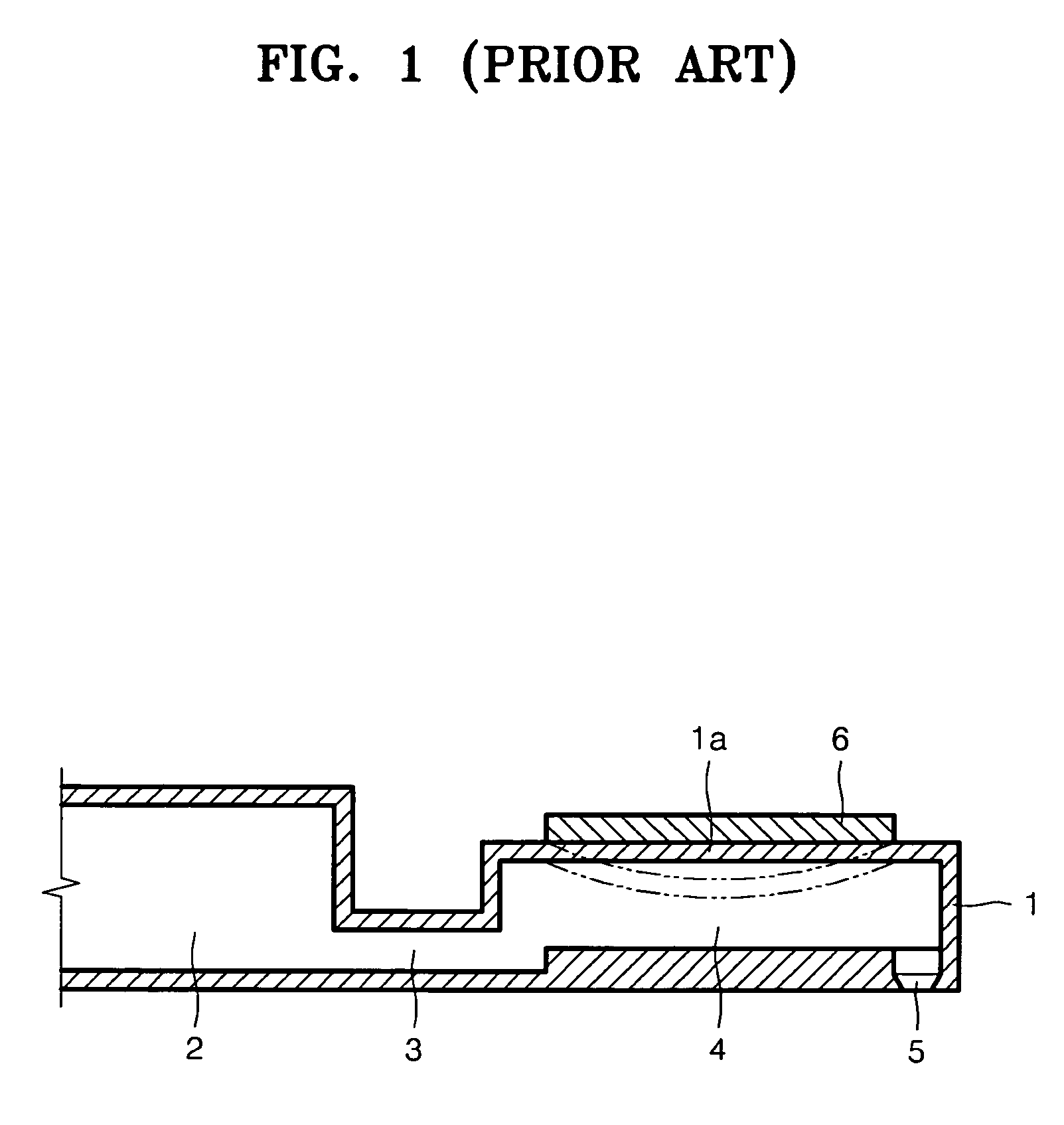
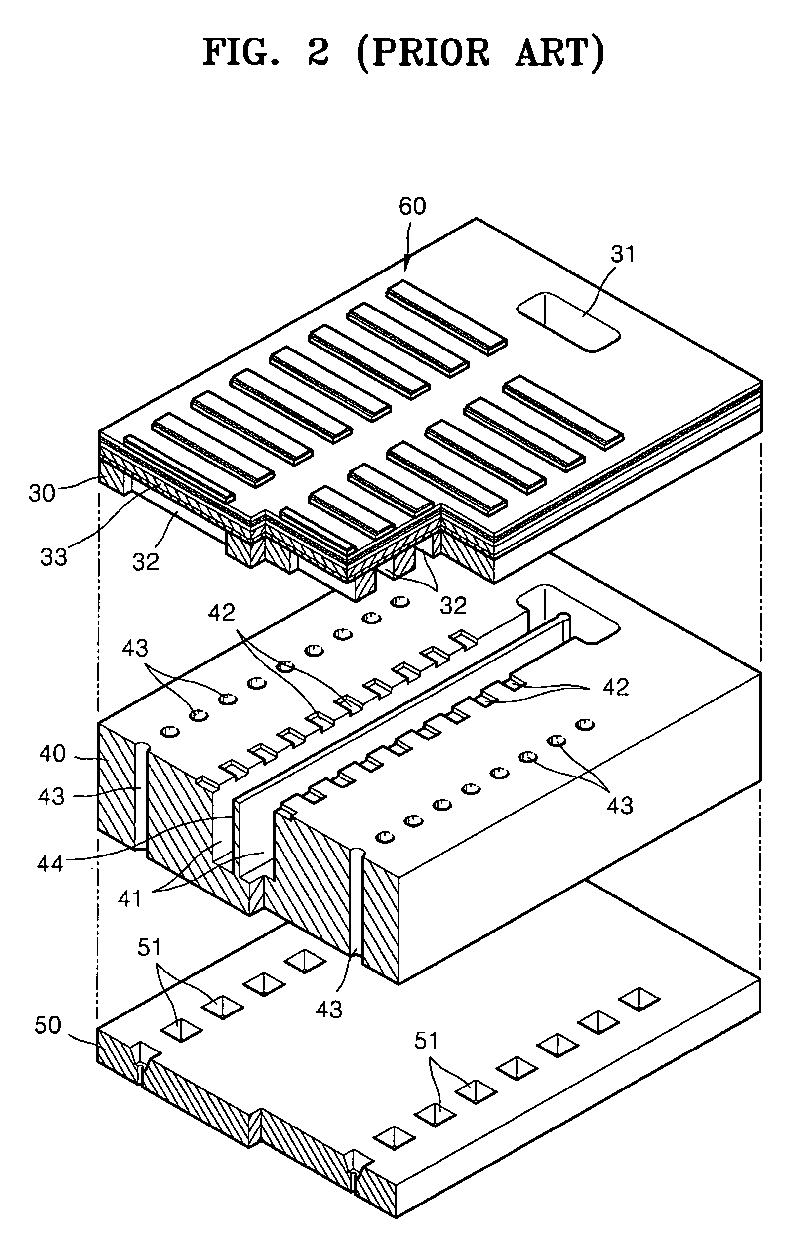
BACKGROUND OF THE INVENTION[0001]1. Field of the Invention[0002]The present invention relates to an inkjet printhead. More particularly, the present invention relates to a piezoelectric inkjet printhead having an improved structure for preventing cross-talk when ink is ejected, and a method of manufacturing the piezoelectric inkjet printhead.[0003]2. Description of the Related Art[0004]An inkjet printer is a device for forming an image on a medium by ejecting ink droplets onto a desired region of the medium. Inkjet printheads can be classified into two types according to the ejecting mechanism of ink droplets: a thermal type inkjet printhead that creates bubbles by heating the ink to eject ink droplets by the expansion of the bubbles, and a piezoelectric type inkjet printhead that includes a piezoelectric material to eject ink droplets by the pressure generated by the deformation of the piezoelectric material.[0005]FIG. 1 illustrates a structure of a conventional piezoelectric inkje...

Claims


Application Information

Patent Timeline
Patent Type & Authority Patents(United States)
IPC IPC(8): B41J2/045B41J2/17
CPCB41J2/055B41J2/14233B41J2/161B41J2/1623B41J2/1628B41J2/1629B41J2/1631B41J2/1632B41J2/1635B41J2/1646B41J2002/14419
Inventor JUNG, CHANG-HOONLIM, SEUNG-MOSHIN, SU-HO
Owner SAMSUNG ELECTRO MECHANICS CO LTD
Why Eureka
Try Eureka