Liquid ejecting head and liquid ejecting apparatus

a liquid ejecting head and liquid ejecting technology, which is applied in printing and other directions, can solve the problems of difficult to discharge air bubbles accumulated in the filter section, failure to discharge air bubbles due to the presence of air bubbles, and dot missing, so as to reduce the effect of unnecessary liquid waste and the reduction of the dynamic pressure of the liquid supply to the reservoir

Inactive Publication Date: 2009-05-26
SEIKO EPSON CORP
View PDF9 Cites 7 Cited by
  • Summary
  • Abstract
  • Description
  • Claims
  • Application Information

AI Technical Summary

Benefits of technology

[0010]An advantage of some aspects of the invention is that it provides a liquid ejecting head and a liquid ejecting apparatus in which discharge failure due to the presence of an air bubble is prevented to reduce unnecessary waste of a liquid.
[0011]According to a first aspect of the invention, a liquid ejecting head includes a head main body including a plurality of nozzle openings that eject a liquid; a supply channel that supplies the liquid from a reservoir unit containing the liquid to the head main body for each nozzle group of the head main body; a filter disposed at a halfway position of the supply channel; a filter chamber that is provided as an enlarged width portion for accommodating the filter; a sub-supply channel that communicates with the upstream side of the filter chamber of the supply channel and that communicates with the downstream side of the filter chamber; and a sub-filter that is provided on an opening of the sub-supply channel, the opening communicating with the upstream side of the filter chamber of the supply channel. According to the first aspect of the invention, in the case where air bubbles are accumulated on the filter, even when the air bubbles are not discharged before supply failure of the liquid or discharge failure of the liquid by the head main body occurs, the liquid can be supplied to the head main body through the sub-supply channel. Accordingly, the supply failure of the liquid or discharge failure of the liquid can be prevented. Furthermore, the liquid can be supplied to the head main body through the sub-supply channel even in a state in which air bubbles are accumulated on the filter. Accordingly, the frequency of a suction operation for discharging the air bubbles on the filter can be decreased, thereby reducing unnecessary waste of the liquid. Furthermore, foreign matter mixed in the liquid flowing through the sub-supply channel, such as fine air bubbles and contaminant matter, can be trapped by the sub-filter, thus preventing the foreign matter from being mixed in the head main body.
[0012]In the liquid ejecting head, the sub-filter is preferably disposed so that a direction intersecting the direction orthogonal to the direction in which the liquid flows through the supply channel is the surface direction of the sub-filter. In the liquid ejecting head, the sub-filter is preferably disposed so that the surface direction of the sub-filter is along the direction in which the liquid flows through the supply channel. In this case, air bubbles accumulated on the sub-filter can be reduced in number. Furthermore, when no air bubbles are accumulated on the filter, flow of the liquid in the sub-supply channel can be prevented.

Problems solved by technology

In such an ink jet recording head, when air bubbles present in ink in an ink cartridge or air bubbles mixed in the ink during attachment or detachment of the ink cartridge are supplied to a head main body, discharge failure due to the presence of the air bubbles, such as dot missing, occurs.
However, it is difficult to discharge air bubbles accumulated in the filter section.
Accordingly, foreign matter such as contaminant matter cannot be trapped by the filter, resulting in a problem of clogging of a nozzle, or the like.
In addition, when large foreign matter flows in the bypass channel, the bypass channel clogs and does not function.
Accordingly, in a state in which air bubbles are accumulated on the filter, supply failure of ink occurs, and the frequency of discharging the air bubbles accumulated on the filter cannot be reduced.
Therefore, unnecessary waste of the ink cannot be reduced.
These problems occur not only in ink jet recording heads that discharge ink but also in other liquid ejecting heads that eject a liquid other than ink.

Method used


Image

  • Liquid ejecting head and liquid ejecting apparatus
  • Liquid ejecting head and liquid ejecting apparatus
  • Liquid ejecting head and liquid ejecting apparatus

Examples


first embodiment

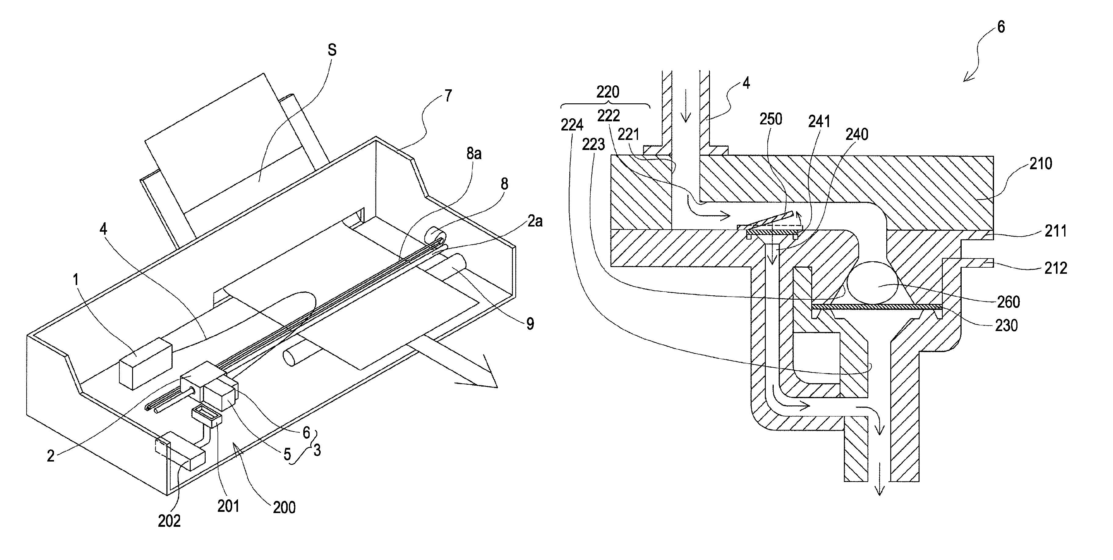
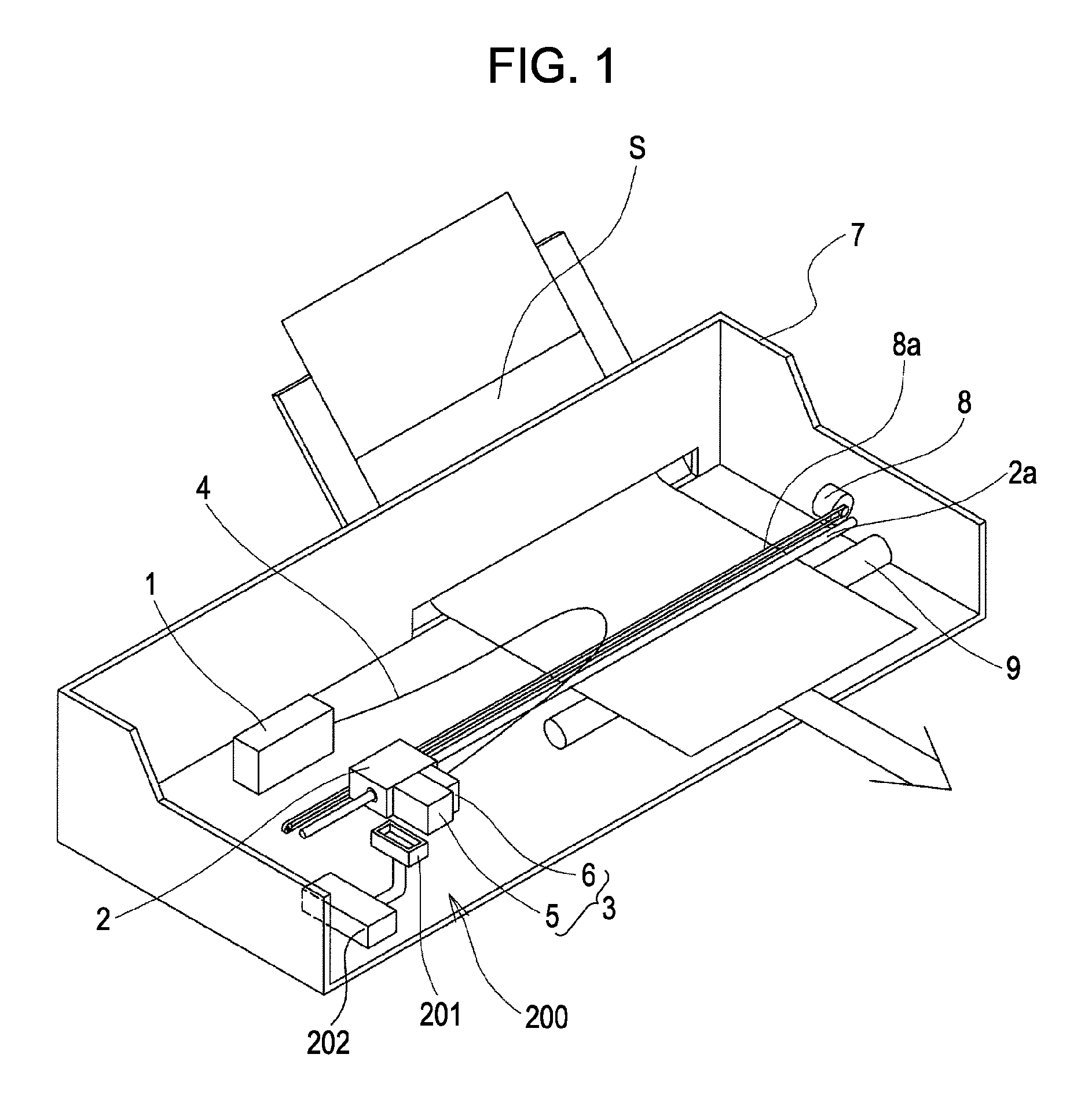
[0026]FIG. 1 is a schematic perspective view of an ink jet recording apparatus according to a first embodiment of the invention. As shown in FIG. 1, in this embodiment, ink supplied from a reservoir unit 1 containing the ink is supplied to an ink jet recording head 3 mounted on a carriage 2 through a supply tube 4. The ink jet recording head 3 includes a head main body 5 including nozzle openings for discharging the ink and a filter unit 6 connected to the supply tube 4 for supplying the ink from the reservoir unit 1 to the head main body 5.

[0027]The carriage 2 mounting the above ink jet recording head 3 is provided in a carriage shaft 2a attached to an apparatus main body 7 so as to freely move in the axial direction.

[0028]A driving force of a drive motor 8 is transmitted to the carriage 2 through a plurality of gears (not shown) and a timing belt 8a, whereby the carriage 2 mounting the ink jet recording head 3 is moved along the carriage shaft 2a. A platen 9 is provided along the ...


PUM


Abstract

A liquid ejecting head includes a head main body including a plurality of nozzle openings that eject a liquid; a first supply channel that supplies the liquid from a reservoir unit containing the liquid to the head main body for each nozzle group of the head main body; a first filter disposed at a halfway position of the first supply channel; a filter chamber that is provided as an enlarged width portion for accommodating the first filter; a second supply channel that communicates with the upstream side of the filter chamber of the first supply channel and that communicates with the downstream side of the filter chamber; and a second filter that is provided on an opening of the second supply channel, the opening communicating with the upstream side of the filter chamber of the first supply channel.

Description

BACKGROUND[0001]1. Technical Field[0002]The present invention relates to a liquid ejecting head and a liquid ejecting apparatus, and in particular, to an ink jet recording head and an ink jet recording apparatus that discharge ink as the liquid.[0003]2. Related Art[0004]In an ink jet recording head, which is a typical example of a liquid ejecting head, in general, ink is supplied from an ink reservoir unit filled with ink, such as an ink cartridge, to a head main body, and the ink supplied to the head main body is discharged from a nozzle by driving a pressure generator, such as a piezoelectric element or a heater element.[0005]In such an ink jet recording head, when air bubbles present in ink in an ink cartridge or air bubbles mixed in the ink during attachment or detachment of the ink cartridge are supplied to a head main body, discharge failure due to the presence of the air bubbles, such as dot missing, occurs. In order to solve this problem, in a known ink jet recording apparat...

Claims


Application Information

Patent Timeline
Patent Type & Authority Patents(United States)
IPC IPC(8): B41J2/175
CPCB41J2/17509B41J2/17563
Inventor OKUBO, KATSUHIRO
Owner SEIKO EPSON CORP
Why Eureka
Try Eureka