
Disk drive device having a motor, and manufacturing method of the motor

a technology of disk drive and motor, which is applied in the direction of mechanical energy handling, dynamo-electric machines, instruments, etc., can solve the problems of large diameter, unsuitable for portable use, and optical disk, and achieve the effect of preventing the disk loading portion from deformation

Inactive Publication Date: 2009-05-26
NIDEC CORP
View PDF14 Cites 22 Cited by
  • Summary
  • Abstract
  • Description
  • Claims
  • Application Information

AI Technical Summary

Benefits of technology

The present invention provides a brushless motor with a reduced thickness and a center axis that is not offset from the center axis of the disk. The motor includes a rotor with a rotor magnet and a rotor holder, and a stator with an armature. A turn table is affixed at the rotor holder for attaching and removing disks, and the turn table has a disk loading portion with a predetermined thickness to prevent deformation of the disk. The rotor holder has a cylindrical portion and an outwardly extending portion that prevents the armature from moving further upward. The technical effects of the invention include a thinner motor and a more stable attachment of disks to the motor.

Problems solved by technology

The optical disk, however, has a large diameter and is not suited for portable uses.

Method used


Image

  • Disk drive device having a motor, and manufacturing method of the motor
  • Disk drive device having a motor, and manufacturing method of the motor
  • Disk drive device having a motor, and manufacturing method of the motor

Examples


Embodiment Construction

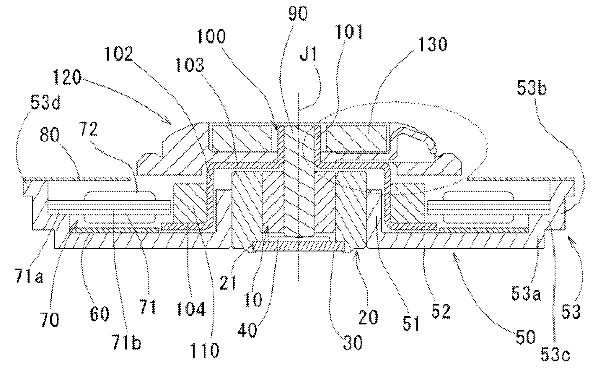
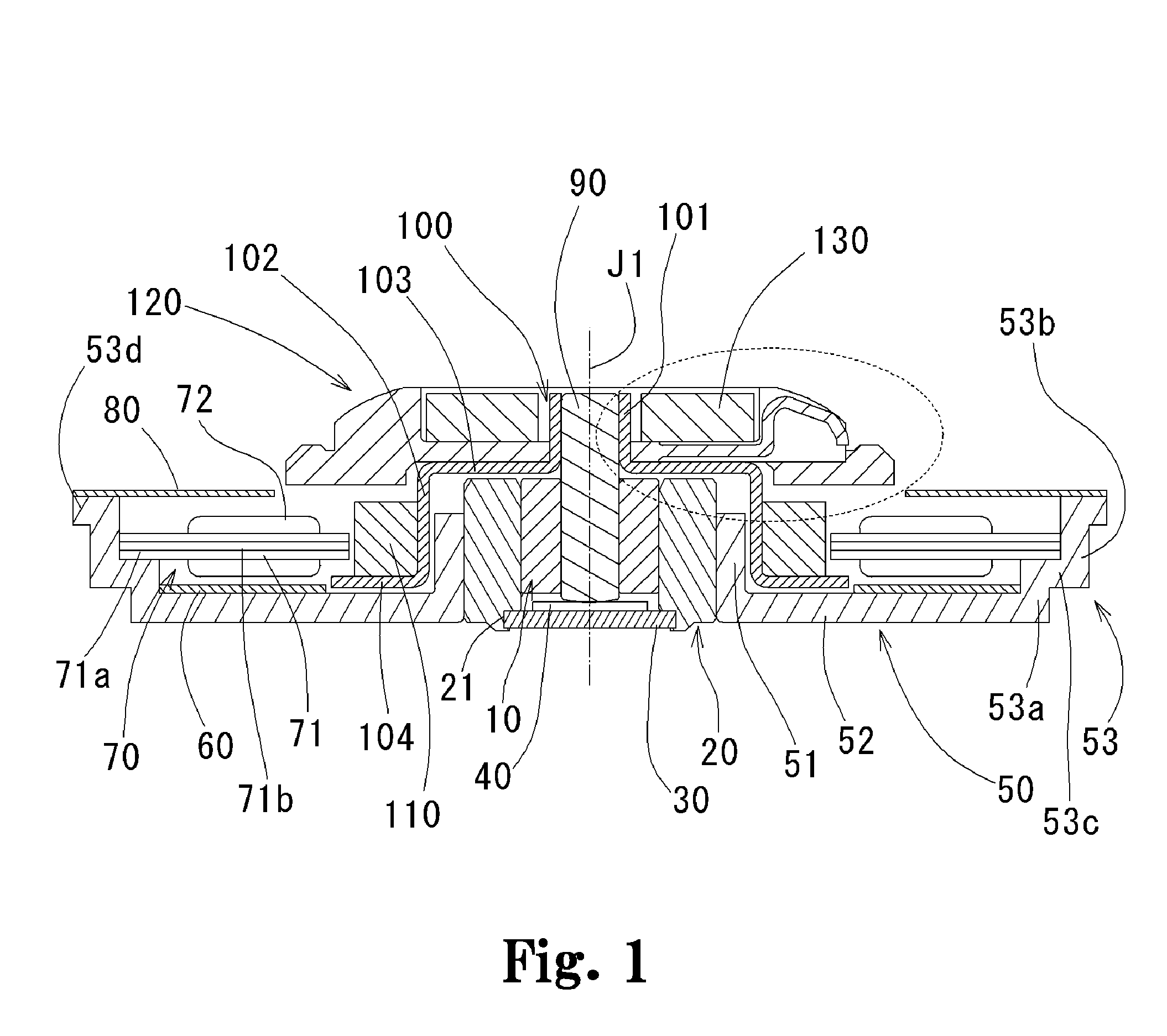
[0023]Hereinafter, an entire structure of a first preferred embodiment of a brushless motor according to the present invention will be described with reference to FIG. 1. FIG. 1 is a diagram showing a cross sectional view, in an axial direction, of the brushless motor.

[0024]A sleeve l0 is a cylindrically shaped bearing made of a sintered material impregnated with oil. A housing 20 for retaining the sleeve 10 therein by an inner circumferential surface of the housing 20 is provided on an outer circumferential surface of the sleeve 10. The housing 20 is constructed such that a lower portion thereof extends below the bottom surface of the sleeve 10. Below the housing 20, an enlarged inner diameter portion 21 is provided. A plate 30 for sealing the inner circumferential side of the sleeve 10 and that of the housing 20 is provided at an inner circumferential surface of the enlarged inner diameter portion 21. A disk shaped thrust plate 40 which is made of a material having superior abrasi...


PUM


Abstract

An inner rotor type motor includes a turn table having a disk loading portion and a central opening portion arranged to allow a disk to be attached thereto and removed therefrom, a rotor concentric with a rotation axis of the turn table, the rotor including a rotor holder having therein a rotor magnet and a cylindrical portion arranged to retain on an outer circumferential surface thereof the rotor magnet, and a stator having an armature arranged to oppose an outer circumferential surface of the rotor magnet via a gap therebetween. The turn table is affixed in an axial direction on an upper portion of the rotor holder, and the disk loading portion is arranged radially outside the cylindrical portion of the rotor holder. A disk loading surface of the disk loading portion is arranged to make contact with the disk, and a bottom portion of the disk loading portion is arranged axially below an area where the turn table and the rotor holder make contact with one another. The disk loading portion has a predetermined thickness in the axial direction, thereby preventing a deformation of the disk loading portion even when the disk is placed thereupon.

Description

BACKGROUND OF THE INVENTION[0001]1. Field of the Invention[0002]The present invention relates to an inner rotor type motor, and more particularly, to a motor having a turntable loaded thereon to which a disk is attached and from which the disk is removed, and to a manufacturing method of the motor. Also, the present invention relates to a disk drive device including the motor.[0003]2. Description of the Related Art[0004]Recently, there is an increased demand for a disk driving device used for driving an optical disk (e.g., CD and / or DVD) to become smaller in size and dimension, and to become portable. The optical disk, however, has a large diameter and is not suited for portable uses. Therefore, in order to achieve portability of the disk driving device, a portable terminal device, or a disk driving device, compatible with an optical disk having a reduced diameter is in demand.[0005]Conventionally, an outer rotor type brushless motor such as one shown in FIG. 9 is used for the disk ...

Claims


Application Information

Patent Timeline
Patent Type & Authority Patents(United States)
IPC IPC(8): H02K11/00
CPCG11B17/0282G11B19/2009H02K7/085H02K7/14
Inventor ICHIZAKI, HIROYUKI
Owner NIDEC CORP
Learn More