
Digital camera and cradle on which the digital camera is mounted

a digital camera and cradle technology, applied in the field of digital camera systems, can solve the problems of troublesome and laborious cable connection, low operability, and inability to obtain the current communication mode settings, so as to achieve the effect of eliminating laborious setting operations and improving operability

Inactive Publication Date: 2009-05-26
FUJIFILM HLDG CORP +1
View PDF15 Cites 44 Cited by
  • Summary
  • Abstract
  • Description
  • Claims
  • Application Information

AI Technical Summary

Benefits of technology

The present invention is a digital camera system that aims to provide high operability and ease of use. The system includes a cradle and a digital camera that can be easily mounted on the cradle. The cradle has a movable portion that can be positioned based on the needs of the user. The cradle generates command signals based on the position of the movable portion and sends them to the digital camera. The digital camera has a signal receiving device that receives the command signals and changes its operation modes accordingly. This eliminates the need for complicated settings and improves the user experience. The cradle can also have a tilting mechanism that allows for easy adjustment of the camera's tilt angle, which in turn changes the functions of the camera for external equipment. This further enhances the user's operability and eliminates the need for laborious setup procedures.

Problems solved by technology

However, a connection using a cable is a troublesome and laborious job.
Therefore, the digital camera is to be mounted on the cradle after setting the communications mode, thereby causing low operability.
Furthermore, there has been the problem that the settings of the current communications mode cannot be obtained until the settings on the camera side are checked.

Method used


Image

  • Digital camera and cradle on which the digital camera is mounted
  • Digital camera and cradle on which the digital camera is mounted
  • Digital camera and cradle on which the digital camera is mounted

Examples


first embodiment

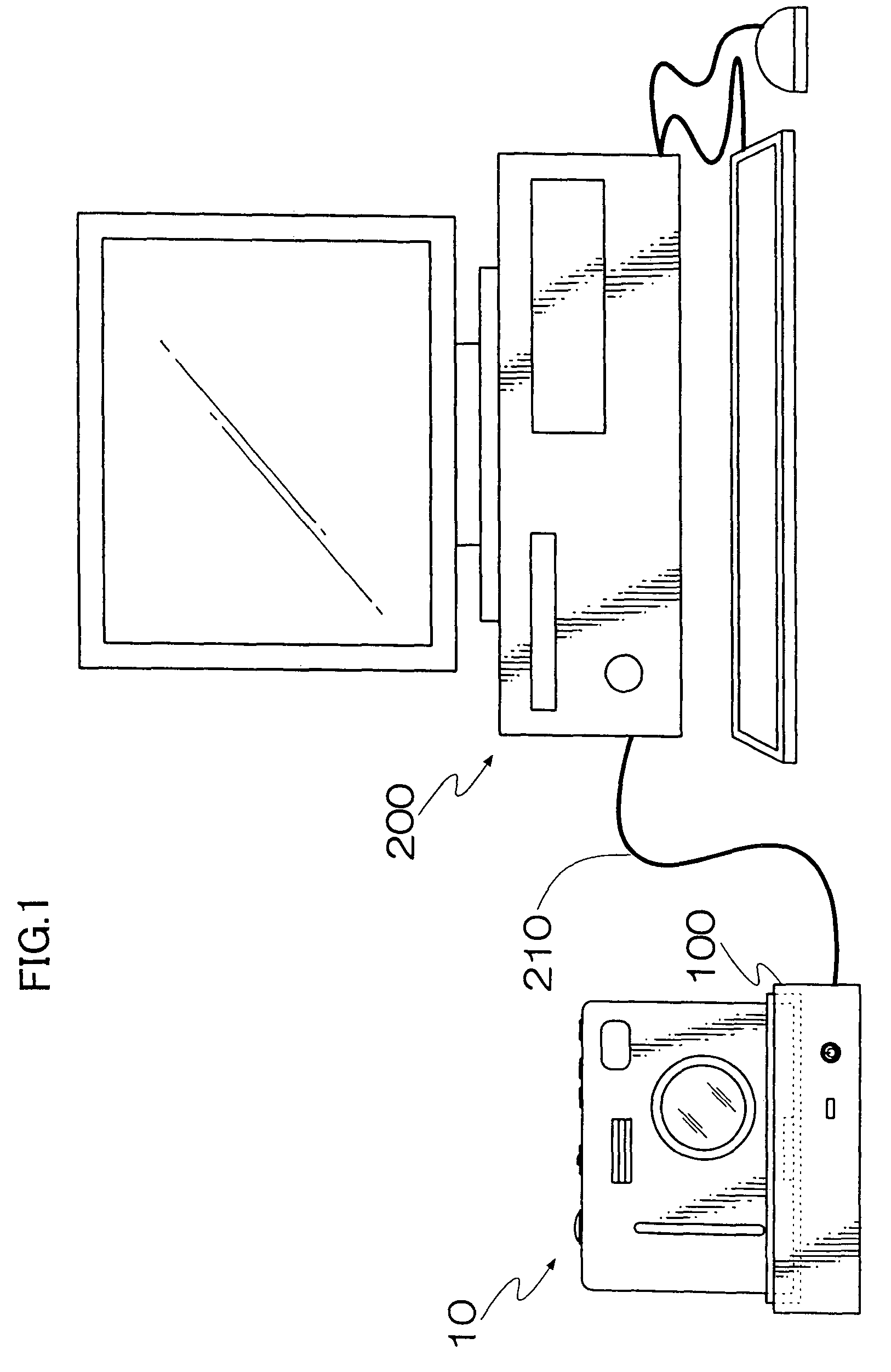
[0040]FIG. 1 is a perspective view showing the digital camera system according to the present invention. As shown in FIG. 1, the digital camera system according to the present embodiment is configured by a digital camera 10 and a cradle 100. The cradle 100 is connected to a personal computer 200 through a communications cable (USB cable in the present embodiment) 210 for bidirectional communications.

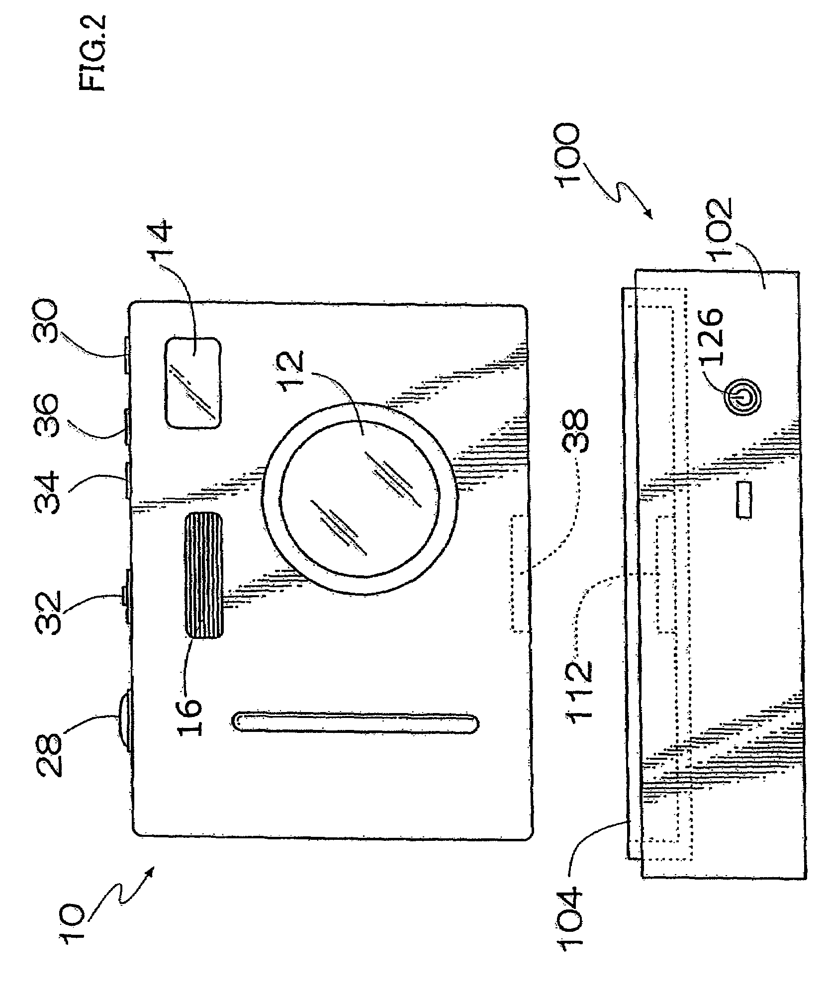
[0041]FIGS. 2 and 3 are front and back views respectively of the appearance of the digital camera 10 and the cradle 100.

[0042]As shown in FIG. 2, there are a taking lens 12, an electric flash light 14, a finder window 16, etc. on the front of the digital camera 10. As shown in FIG. 3, there are a finder 18, a cross button 20, a menu / OK button 22, a cancel button 24, a liquid crystal monitor 26, etc. on the back of the digital camera 10. On the top surface of the digital camera 10, there are a shutter-release button 28, a power button 30, a mode switch 32, a playback button 34, and a reve...

second embodiment

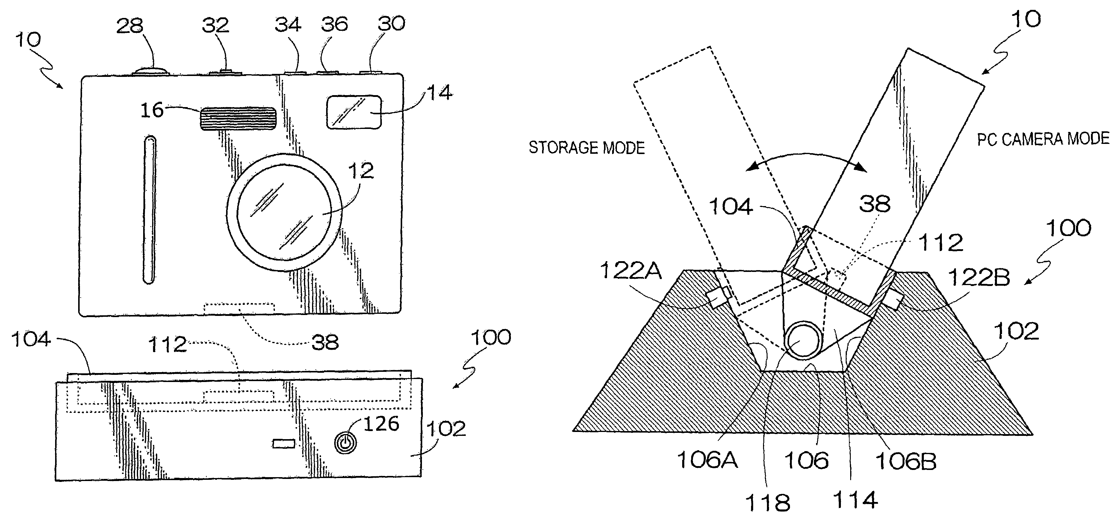
[0064]FIG. 8 is a front view of the appearance of the digital camera 10 and a cradle 300 according to the digital camera system of the present invention.

[0065]As shown in FIG. 8, in the digital camera system according to the second embodiment, the digital camera 10 can be mounted on the cradle 300 with facing either forward and backward with respect to the cradle 300. Then, according to the direction of the digital camera 10 mounted on the cradle 300, the storage mode and the PC camera mode of the USB-connected digital camera 10 can be switched.

[0066]On the top surface of the cradle 300, a mounting unit 302 on which the digital camera 10 is mounted is formed, and the cradle connector 112 is provided at the center of the bottom surface of the mounting unit 302.

[0067]On the bottom surface of the mounting unit 302, a pair of holes 304A and 304B are formed symmetrically about the cradle connector 112 as shown in FIGS. 8 and 9. The holes 304A and 304B are provided with switches 306A and ...

third embodiment

[0079]FIGS. 10(a) and 10(b) are sectional views of the side showing the configuration of the digital camera 10 and a cradle 400 according to the digital camera system of the present invention.

[0080]As shown in FIGS. 10(a) and 10(b), in the digital camera system according to the third embodiment, a foldable leg 402 is provided on the bottom of the cradle 400 so that the tilt angle of the digital camera 10 mounted on the cradle 400 can be varied. By folding and extending the foldable leg 402, the storage mode and the PC camera mode of the USB-connected digital camera 10 can be switched.

[0081]A mounting unit 404 on which the digital camera 10 is mounted is provided on the top surface of the cradle 400, and a cradle connector (not shown) is provided at the center of the bottom of the mounting unit 404.

[0082]On the other hand, a recess 406 is formed on the bottom of the cradle 400, and the foldable leg 402 can be stored in the recess 406. The base portion of the foldable leg 402 is provi...


PUM


Abstract

A digital camera is mounted on a camera mounting unit of a cradle, and supported as swayable. When the digital camera is tilted forward, a front switch is turned on, and a command to change into a storage mode is issued from a switch determination circuit to the digital camera. When the digital camera is tilted backward, a back switch is turned on, and a command to change into a PC camera mode is issued from the switch determination circuit to the digital camera.

Description

BACKGROUND OF THE INVENTION[0001]1. Field of the Invention[0002]The present invention relates to a digital camera system, and more specifically to a digital camera system in which a digital camera is connected to external equipment such as a personal computer via a cradle.[0003]2. Description of the Related Art[0004]A digital camera can be connected to a personal computer so that a shot image data can be fetched to the personal computer.[0005]Generally, a cable is used in connecting a personal computer to a digital camera. However, a connection using a cable is a troublesome and laborious job.[0006]Accordingly, a camera system of connecting a digital camera to a personal computer using a cradle is proposed to simplify the job of connecting a personal computer to a digital camera. The system enables a digital camera to be connected to a personal computer by mounting the digital camera on a cradle connected to the personal computer through a cable.[0007]Recently, a digital camera has ...

Claims


Application Information

Patent Timeline
Patent Type & Authority Patents(United States)
IPC IPC(8): H04N5/225H04N1/00H04N5/232
CPCH04N1/00204H04N1/00241H04N1/32496H04N5/232H04N5/23245H04N2101/00H04N2201/0058H04N23/66H04N23/667H04N23/00
Inventor TAKAHASHI, KIMIHIDE
Owner FUJIFILM HLDG CORP
Learn More